- 133Xe
- 127Xe
- 81mKr
- 99mDTPA
- Technegas
P or V first |
Gamma Energy keV |
Washout |
Room Pressure |
|
133Xe |
Ventilation |
80 |
Yes |
Negative |
127Xe |
Perfusion |
172, 203, 375 |
Yes |
Negative |
81mKr |
Perfusion |
190 |
No |
N/A |
Technegas |
Ventilation |
140 |
No |
N/A |
99mTcDTPA |
Either |
140 |
No |
N/A |
T1/2 |
Views |
Cost |
|
133Xe |
5 days |
1 (POST) |
Average |
127Xe |
36 days |
1 (POST or best view) |
More than 133Xe |
81mKr |
13 seconds |
Multiple |
Very Expensive |
Technegas |
6 hours |
Multiple |
Unknown |
99mTcDTPA |
6 hours |
Multiple |
Less than X133 |
- When the radiopharmaceutical is a gas and has a significantly long T1/2
- 133Xe and 127Xe require a negative pressure room
- 127Xe may or may not be available - https://www.isotopes.gov/products/Xenon
- Because 81mKr has a short T1/2, a negative pressure is not necessary
- It looks like 81mKr may be available in the UK - http://kr81m.org.uk/
- Technegas and 99mTcDTPA are not gases, therefore a negatively pressured room is not necessary
- Criteria regarding a negatively pressured room
- Xenon delivery system contain traps made of charcoal and is placed at the exhaust port
- Exhaled xenon gas that leaves the trap must be vented to certain concentration levels
- Restricted area maximum concentration is 1 x 10⁻⁵ μCi/ml
- Non-restricted area maximum concentration is 3 x 10⁻⁷ μCi/ml
- If the sum of all exhaust rates is greater than the sum of the air supply coming into the room, then the room has negative pressure
- Flow is measured in cubic feet per minute (CFM)
- CFM must be measured quarterly
- Calculating the room exchange rate - link
- The charcoal trap must be measured monthly to assure that you are below the maximum concentration level
- Collect activity from a Xenon study by placing a plastic bag around the exhaust port
- Measure the activity with your gamma camera
- According to Biodex's Pulmonex system, the charcoal filter is good for 30 - 50 studies completed per month
- It is easily replaced
- The negative pressured room must also be tested for the time it takes for a xenon spill to be ventilated from the room
- If a xenon spill occurs, the door must be shut in order to contain the gas
- Once the air has been completely re-circulated, the gas removed, the door may then be opened
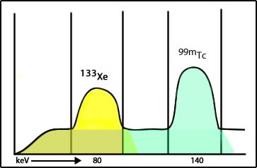
- The concern relates to a concept known as cross talk
- 133Xe has the lower gamma energy
- If 99mTcMAA is completed first, the gamma energy from 99mTcMAA spills into (cross talk) the 133Xe window adding unwanted counts in the image. This would also be defined as Compton scatter from the 99mTc atoms
- If 133Xe is completed first, this does not become an issue
- CAVEAT: Literature cites some "evidence" to indicate that cross talk is not a problem and that the computer subtraction technique will eliminate/solve the issue. I disagree.
- Rationale: if the perfusion images are normal, then there is no reason to continue with the ventilation procedure (if there is a cold defect in perfusion that raises the question of PE)
- Cold Defects - Matched and mismatched
- Matched defects indicate COPD (or related). This ventilation defect may also affect the vascular supply to the same area, resulting in cold perfusion and cold ventilation defect. This would occur if the vascular and bronchial are both necrotic or badly damaged
- Mismatch would indicate PE (cold perfusion/hot ventilation)
- In order to complete the ventilation images, consideration of the gamma energy on the ventilation agents must be considered (refer to table)
- 127Xe and 81mKr have higher energy gamma than 99mTc. Hence ventilation would follow perfusion
- Why are these two agents not routinely used? (cost and availability)
- Requires a negative pressure room
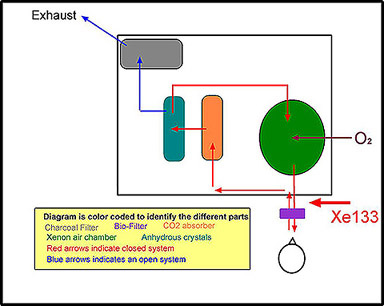
- Requires a special apparatus for administration, Xenon Delivery System (see the diagram below)
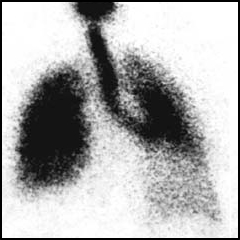
- The patient is set up so that the posterior portion of the lungs are imaged - NOTE: can only be taken in one projection
- 133Xe is usually done before the perfusion study; however, if 127Xe is used, then ventilation may follow perfusion (note energy)
- If 127Xe is used, only one modification must be made with the delivery device, and that is it must have increased shielding for the higher energy gamma
- There are three phases to the study
- Initial Breath (closed system) - inhalation of a radioactive bolus which identifies total lung capacity
- The patient inhales a bolus of 133Xe through a bio-filter
- The patient holds his/her breath for 20 seconds
- The delivery system is defined as closed (refer to diagram)
- When the patient exhales the gas, it enters the delivery system
- The study enters its second phase
- Equilibration (Closed system) - Gas is continually recycled to the patient, filtering out CO2 on exhalation and enriching the inhalation with O2 until the concentration of Xenon in the lungs = the concentration in the ventilation system (indicates lung volume)
- Note the pathway of the exhalation: CO2 absorber, anhydrous crystals, xenon chamber, bio-filter, patient
- CO2 absorber - is made of soda-lime to removes CO2 and prevents acidosis
- Defined as a closed system - follow the red arrows
- While the patient is breathing, air and xenon follow the red arrows
- Additional O2 is added to the closed system
- One minute images are taken for two to three minutes
- Washout - The ventilation system is then opened, and the exhaled gas leaves the patient and exits the ventilation system. The faster the xenon clears from the lung, the better ventilation is in the lungs. Poorly ventilated areas, that contain COPD, will have residual xenon remaining in the lungs for an extended period of time (greater than several minutes)
- As the patient exhales, gas follows the red arrows to blue arrows
- The system is defined as an open-system
- Charcoal filter traps the Xenon as it leaves the system
- One minute images are taken for three to five minutes
- The patient is kept on the system until all the gas has washed out of the lungs
- Delayed washout or residue activity indicates COPD
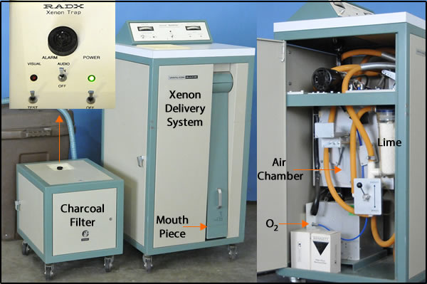
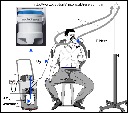
- Here is an example of what a Xenon Delivery System looks like
- Close up of a Pulmonex II system
- Because of the cost and availability of the Rb/Kr generator, many imaging centers do not use this procedure
- Consider the purchase of 1 generator per day times 365 days per year
- Also, consider the limited shelf life of the Rb/Kr generator
- 81Rb T1/2 = 30.5 minutes and has a useful shelf life of approximately 6 hours
- 81mKr T1/2 = 13 seconds
- Gas is continually inhaled while the patient is being imaged
- The inhaled gas reaches an equilibrium count rate that is proportional to the ventilation
- Because the energy is higher than Tc99m, perfusion maybe completed first
- Images may be taken at any angle in which the perfusion defect is noted
- Negative pressured room is not required because of the short T1/2 of 81mKr
- Because of the limited counts in the 81Rb generator after 3 PM (note 30.5 minute T1/2) an alternative form of ventilation must be considered
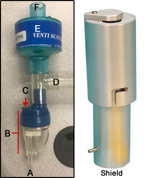
- Here is an example of an 81mKr Delivery system. Image rollover may not work in Bb
- 99mTcDTPA is injected into the nebulizer (refer to diagram)
- O2 enters the nebulizer, converting liquid (99m TcDTPA) into small liquid droplets via an ultrasound or positive-pressure nebulizer
- Droplet size smaller than 2.0 μm reaches the alveoli
- The patient inhales, and droplets coat the inside of the lungs
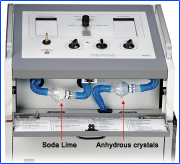
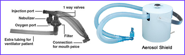
- Here is another aerosol system, Venti-Scan Radio-aerosol Administration System made by Biodex
- O2 port
- Nebulizer
- IV port
- Tubing goes to mouth
- Filter
- Place to attach tail
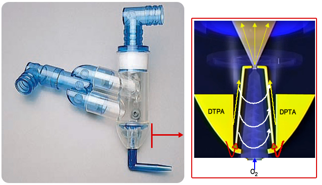
- Swirler Aerosol System by Amici
- How how is a mist generated?
- 99mTcDTPA is injected into the swirler compartment
- O2 is forced into the chamber that starts the swirler momentum
- This forces the reservoir of DTPA to be sent up the tubes (red arrow), ending in a spray of droplets (yellow arrow)
- The spinning action of the swirler causes the mist to spin in a vortex
- Larger particles hit the dome above the yellow arrow and the walls of the nebulizer
- This generates more uniform droplets in the range of one micron
- Closer look at the Swirler
- Concern related to aerosol droplets having extensive uptake in the bronchial tree depends on particle size, airflow rates, and turbulence
- The delivery tubing filters out larger droplets (10 to 15um), while droplets that are <0.1 μm escape as expired air
- Note the one-way valve in the diagram allows the expired air (droplets) to be trapped by the filter
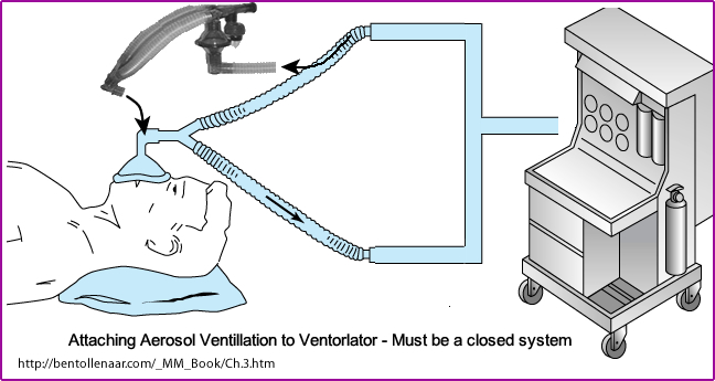
- Note the extra tubing for patients that are on ventilators (tubing is called the "tail")
- Dose
- 3 to 5 ml placed into the nebulizer
- Approximately 35 mCi (if the study is done before perfusion)
- No more than 10 to 15% of the dose reaches the lungs, however, based on the amount of type the drug is administered, the dose may actually be less
- Administration imaging the aerosol (ventilation) procedure
- Usually, the patient breaths on this system five minutes
- After ventilation, images are taken for approximately 150k counts or five minutes
- In patients with severe COPD or other ventilation problems, mucous plugs prevent the droplets from reaching the alveoli. In addition, the mucous plugs appear hot (droplets adhere to the plugs). This may reduce diagnostic accuracy. (What happens if a mucous plug prevents droplets from entering a segment in the lung that appears cold in perfusion)
- If a patient suffers from COPD, numerous mucous plugs will appear on the scan. I refer to this condition as "hot grapes."
- If perfusion is done first, then the ventilation dose must be significantly higher (60mCi or greater) and the perfusion dose must be significantly less (1 mCi). However, most clinics perform ventilation prior to perfusion.
- Problem with the 99m Tc energy is noted when both perfusion and ventilation use the same radionuclide
- The number of counts coming from whichever procedure is done second must be at least 3 times greater than the counts coming from the first procedure
- As an example, if ventilation is done first and too many counts come from the ventilation images, then activity from the ventilation images may shine through into the perfusion image. If a segment in the lung contains a PE, it would normally look cold in a perfusion defect. However, if a ventilation image contains too many counts, activity from the ventilation image may shine through, causing the perfusion image to contain activity in the area of the PE. This could lead to a false negative diagnosis
- Improving the quality of the aerosol image
- The patient should be dosed in the upright position, which allows for better distribution of the droplets
- Patients with ventilators require a special hookup
- The ventilation system is considered a closed system. The pressure generated by the ventilator must be able to inflate the lungs
- Therefore, the aerosol system must be attached in such a way that the system remains closed. This is what is being demonstrated in the image above
- Patients on ventilators present additional difficulty
- An increased mucous build-up in the main-stem bronchi may require the patient to be suctioned prior to dosing (reducing the clumping of activity in the main stem bronchi)
- A 10% concentration of ethanol to 99m TcDTPA improves the distribution of the particle by reducing the surface tension on the particle and increasing its density (Journal of Nuclear Medicine: 26(6):643-6, 1985 Jun)
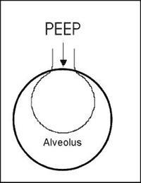
- Positive end-expiatory pressure (PEEP) is the pressure applied by a ventilation device. Excessive pressure (causing turbulence) of greater than 20 may cause abnormal clumping of the droplets in the main stem bronchi. Reducing PEEP while the patient is being dosed with 99m TcDTPA may reduce this effect and improve the quality of the scan
- Diagram shows how PEEP effects the alveolus
- Note: When there is excessive activity in the main stem bronchi, image quality is reduced, thus reducing being collected by the area of interest - the lungs.
- Technegas
- This radiotracer is an ultra-fine micro aerosol, graphite coated 99mTc atoms. They care called "Bucky balls"
- The diameter range is 5 to 35 nm
- It is a hexagonal crystal of native 99m Tc metal that is "shrink-wrapped" in a graphite
- 7 to 10 mCi dose
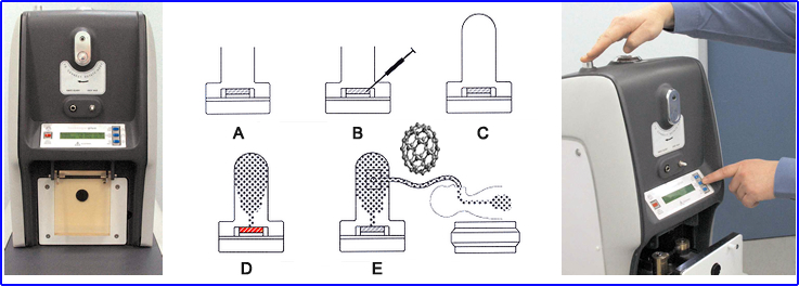
- How are Buckyballs made?
- (a) Turn Argon flow on and place crucible into Technegas generator
- (b) 99mTcO4- is placed into alcohol moistened graphite crucible
- (c) 6 L shielded chamber is then closed, and simmer stage is initiated
- The crucible is heated to evaporate all the liquid and air within the chamber. This replaces the Argon
- (d) Select the start button, and a 6-minute process to produce Buckyballs is initiated
- Unit starts "simmering" process @ 1500oC
- Then for 15 seconds, the "burn" stage generates a temperature of 2500o C
- Creating the Buckyballs
- (e) The patient then inhales via an attached breathing apparatus 2 to 3 times, and approximately 1.0 mCi dose is administered
- Because the particles are hydrophobic and chemically inert, they remain lodged in the alveoli
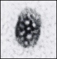
- This is what a Buckyball looks like under an electron microscope (http://jnm.snmjournals.org/content/32/11/24N.full.pdf)
- This ventilation procedure is performed prior to the perfusion study
- Multiple images can be taken (just like 99mDTPA)
- Technegas on YouTube - Note the ability to determine the amount of ventilation in different regions of the lung
- Technegas manual
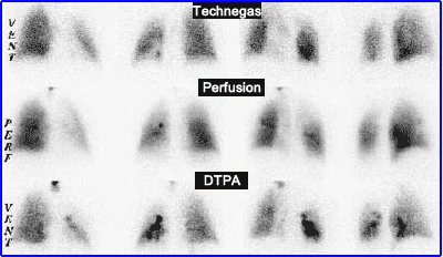
- Comparison of Technegas to DTPA
http://www.uky.edu/Pharmacy/research/lunab25b.jpg
http://lungspect.com/generator/howtousethegenerator.html?showall=1 (no longer online)
http://www.veccsa.com/en/Technegas.htm