- A BGO system has its timing window set between 4 to 12 nsec
- Hence, as long as the two photons arrive within the timing window an LOR is defined and a prompt event is recorded
- If you could significantly reduce the the timing window you would be able to extrapolate back the original location of the annihilation event based on when the two photons arrive
- The other element to this equation is scintillation decay time of the crystal. Why is this a problem with BGO?
- Given the right software/hardware the timing window can be significantly reduced to as little as 0.6 nsec. The critical factor is to apply the right crystal. To do this you must have a crystal with a compatible decay time. Further more it also system's sensitivity. Will this also improve count density?
- Let us look at the types of crystals and their decay time (link)
- BGO crystal has a 300 nsec decay time for scintillation
- LYSO crystal has a 40 nsec decay time
- BaF2 crystal has a 0.6 to 0.8 nsec decay time
- The shorter the decay time the quicker the excited electron can move back into its resting state. This helps determine the general location of the annihilation event
- In today's technology we are at the point where a 70 cm LOR can be cut down to around 9 cm length
- Is 9 cm or less still too long a length to really make a difference?
- Absolutely not!
- Without TOF all LORs must be back-projected through their entire path
- This allows for more scatter and random events
- However, application of TOF improves
- Spatial resolution
- Reduction of scatter and random events
- Has an improved signal to noise ratio (SNR)
- Consider size of the body habitus and apply TOF with scatter
- The larger the diameter of the patient the greater the scatter. As the diameter increases photons have to travel greater distance with an increase greater amount of Compton interaction. Why does this statement mean?
- If TOF is applied, image quality improves via the reduction of scatter. In fact, larger patients' benifit when TOF is applied, as this relates to the fact having an LOR that is only 9 cm in lenght vs 70 cm
- How does scatter and size relate? Without the application of TOF a 120 kg patient's S/N ratio would be 6 times worse when compared to someone who weighed 50 kg
- In addition the larger patient will have more attenuation, requiring an increase in scanning time to achieve an acceptable count density.
- End results - TOF application with a larger patient improves image quality 6 to 1 ratio via SNR
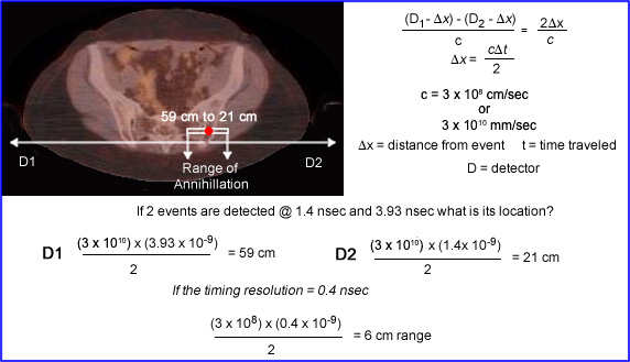
- The above diagram demonstrates the TOF principle
- Red dot represents the exact location of the annihilation event which is approximate location. Consider it a mean location. On either side of the red dot is its 9 cm LOR. The key is to calculate the LOR is to know when each photon event arrives at the coincident ends of the detector
- This example shows D1 detected @ 3.93 nsec and D2 photon arriving at 1.4 nsec
- Multiply these two values individually by the speed of light, divide by 2 gives you the distance the photons traveled, 59 cm and 21 cm respectively
- Now take the timing resolution of 0.4 nsec and multiple that by the speed of light and divide by 2. This gives you range of where the expected annihilation occurred, 6cm. Or it would between 56 cm and 18 cm
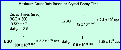
- As the decay shortens the amount of counts that can detected increases
- Compare above BGO to LYSO to BaF2
- Note BaF2 crystal can accept more photons events when compared to the other two crystal types
- This also indicates greater scintillation efficiency that reduces acquisition time
- Crystal
- Short decay time - LSO (LYSO) or better type of crystal
- Highlight output
- Adjust the timing window downward
- PMTs and related electronics requires faster processing, further reducing the time interval
- Image acquisition and reconstruction must be done in 3D list-mode with iterative reconstruction. This allows for better temporal resolution, however, the computer crunching is very intensive
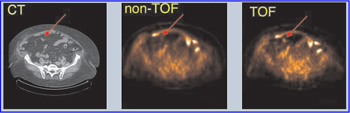
- The above data shows the application of TOF in a 3-D PET image. Note the red arrow is pointing to an additional "hot spot" not seen in the "non-TOF." TOF definitely improve image quality, based on the example provied
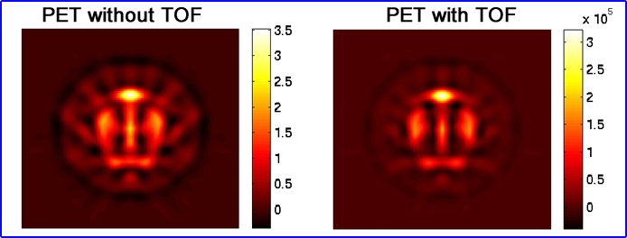
- Consider both images above, what improvement do you see when TOF is applied?
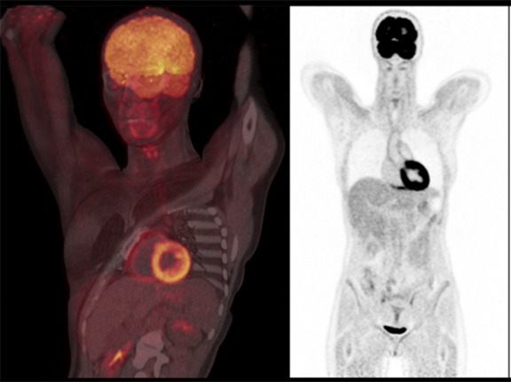
- The above images is data acquired from Siemens PET/CT system applying their "latest" TOF technology (6/2018)