VHDL Compilation and Simulation with ModelSim


1. What you will learn

    1.1 How to create a working directory for the VHDL tools.
    1.2 How to compile a VHDL description.
    1.3 How to simulate the VHDL description.

2. Getting started

    This tutorial and those that follow it assume you are familiar with the Unix environment and commands within it to create directories, list, copy, and move files, etc. Knowledge of a text editor available on Unix systems like vi or jove is also required. If you are not familiar with Unix, it is recommended that you obtain the relevant take-outs from University Computing Services on these subjects and study them. or see the Basic Introduction to Unix available on-line.

    This tutorial also assumes that you are familiar with the VHDL language itself, or are in the process of learning it. Consult the VHDL tutorial available from the tutorial web page if you are unfamiliar with VHDL.

    2.1 First, you should create a separate directory under your home directory to hold the designs for this tutorial:

>> mkdir tutorial

>> cd tutorial

    The ModelSim tool needs a work directory (VHDL library) for the compiled VHDL files. Create this directory with the following command:

>> vlib work

3. Examine and compile the code for this lab

    3.1 Using your favorite text editor, create a file called package.vhd with the following contents:

      PACKAGE resources IS
        -- user defined enumerated type
        TYPE level IS ('X', '0', '1', 'Z');
        -- type for vectors (buses)
        TYPE level_vector IS ARRAY (NATURAL RANGE <>) OF level;
        -- subtype used for delays
        SUBTYPE delay IS time;
      END resources;

    3.2 Compile the VHDL code:

>> vcom package.vhd

>> vcom and2.vhd

4. Simulate the compiled code

    4.1 Start up the ModelSim simulator

>> vsim and2 &

    4.2 View the waveforms of the selected signals by selecting, in the signals window, View->Wave->Signals in Design. Use the left mouse button to pull down the menu. This will create a wave window that looks like a graph, with the signals on the vertical axis and the time along the horizontal axis as shown below:

    4.5 Add some additional forces and run the simulation by typing the following commands into the main window:

      VSIM 5>force -freeze /and2/a 1 0, 0 20
      VSIM 6>force -freeze /and2/b 1 0
      VSIM 7>run 40

    After using the Zoom->Zoom Full command in the wave window, it should look like the one below:
    4.6 Quit the simulator by typing quit in the main window and confirming yes in the dialog box.

5. Create, compile and simulate the D Flip Flop code

    5.1 Using a text editor, create a file called dff.vhd which contains the following code:

      USE work.resources.all;

      ENTITY dff is

        GENERIC(tprop : delay := 8 ns;
          tsu : delay := 2 ns);

        PORT(d : IN level;
          clk : IN level;
          enable : IN level;
          q : OUT level;
          qn : OUT level);

      END dff;

      ARCHITECTURE behav OF dff IS

        BEGIN

          one : PROCESS (clk)

            BEGIN
              IF ((clk = '1' AND clk'LAST_VALUE = '0') AND -- rising clock edge
              enable = '1') THEN -- ff enabled
                IF (d'STABLE(tsu)) THEN -- check setup
                  IF (d = '0') THEN -- check valid input data
                    q <= '0' AFTER tprop;
                    qn <= '1' AFTER tprop;
                  ELSIF (d = '1') THEN
                    q <= '1' AFTER tprop;
                    qn <= '0' AFTER tprop;
                  ELSE -- else invalid date
                    q <= 'X';
                    qn <= 'X';
                  END IF;
                ELSE -- else no setup
                  q <= 'X';
                  qn <= 'X';
                END IF;
              END IF;
          END PROCESS one;

      END behav;

    5.2 Compile the dff.vhd file:

>>vcom dff.vhd

    5.3 Simulate the DFF:

>>vsim dff &

    5.6 Quit the simulator by typing quit in the main ModelSim window.

6.0 Run the dff simulation again, using a do file

    As mentioned previously, you can use a script file, called a do file, to automate tasks like repetitive simulations for debugging purposes. The syntax of the commands for each action you want the tool to do can be looked up in the ModelSim documentation, but a better approach is to simply execute the command once in the actual tool, and then capture the resulting command from the main window into the do file.

    6.1 Using a text editor, create a text file, called dff.do , that contains the following commands:

      add wave -r /*
      force -freeze /dff/clk 0 -repeat 20
      force -freeze /dff/clk 1 10 -repeat 20
      force -freeze /dff/enable 1
      force -freeze /dff/d 0, 1 15, 0 49
      run 100

    6.2 Start the simulation of the dff again:

>>vsim dff &

    6.3 Execute the dff.do file by either using the Macro->Execute Macro... item from the main menu and selecting the dff.do file in the dialog box that comes up, or typing the following into the main window:

      VSIM 1>do dff.do

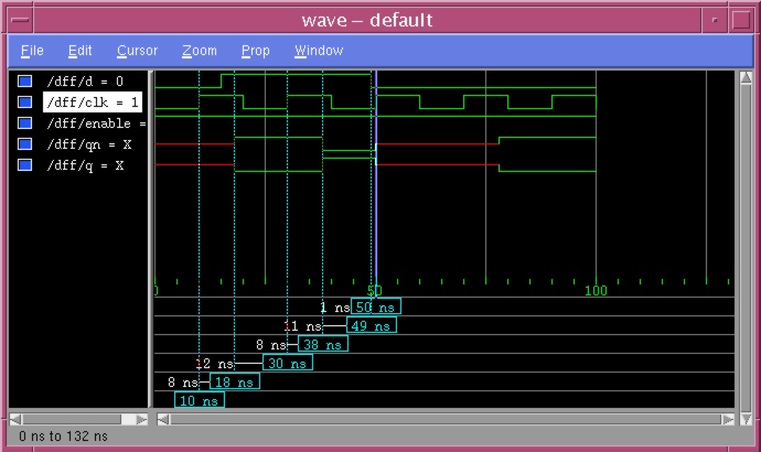
    A wave window with the same simulation results you got above (minus the cursors) should appear.

    6.4 Quit the simulator by typing quit in the main ModelSim window.