MPLAB Tutorial
1.2. How to link the files necessary to build a hex file.
1.3. How to simulate operation of the file.
1.4. How to emulate the microcontroller using MPLAB ICE 2000.
1.5. How to program the microcontroller using the BPMICROSYSTEMS BP-1400.
2.3. Open the arm.c file in the notepad to examine it.
This program generates a pulse for each of the three movements of the robotic arm. The robot operates on a pulse that is transmitted to each servo. The pulse can be between .5 and 2.5ms. A 1.5ms pulsewidth centers the servo. The program calls two header files. One for the 17C44 microcontroller and the the other for the delays. The define statements are constants that are inserted into the body of the code when it is compiled and do not count as memory. Any constant you want to use should be a define statement. All of the variables are defined and set to intial values to center the robotic arm. DDRC = 0x00 sets port C as an output. The output pulses will control the robotic arm. A high signal is generated and the code then goes through a delay, the length of which determines the generated pulse width. The output is then set low. This process is repeated for the other two servos in the arm. The value of the three pulses is added and then subtracted from 10 ms to generate the overall loop delay. This insures a stable pulse repetition rate.
3.3. Click on arm.hex and then click on Node Properties. The Node Properties box will come up. Change the Language tool to MPLINK. Click OK.
3.4. In the Edit Project box click Add Node.
Choose folder
C:\Students\<user>\tutorial\arm\
click on the
arm.c file and click OK.
4.1. Add a trace of the "yaw" variable in the program by selecting
Debug->System Reset. Select Window->New Watch Window.
In the window type yaw and click Add. The default value is Hex.
If you want to change it click on properties and then click on decimal.
Do the same with pitch and grip. Click OK.
4.3. Click on Debug->Run->Step or push the F7 key.
Push the F7 key a few times and several windows will open as the program
steps into other ares of the code. The screen will look like the
following:
As you push F7 you should see the program stepping through the lines of the program.
4.4. Double click on the RD1(H) button. The program will pass over the if up loop. It should go down into the if down loop. As you keep pushing F7, it will start the delay loop and bring up another window dy100tcx.asm. This is the code for the delay of the pulse width to drive the robotic arm. At this point, single stepping the program is no longer useful as it would take too long to run through the entire delay. Save and exit the program.
5.1. Turn on the MPLAB ICE 2000. Start the MPLAB Program.
5.2. Plug emulator into test board socket carefully. Assure the power supply voltage is set at 5.0 volts and connect the leads to the control board.
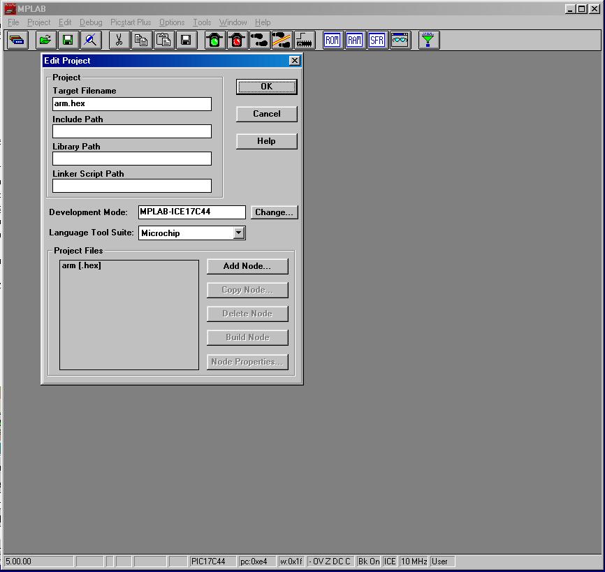
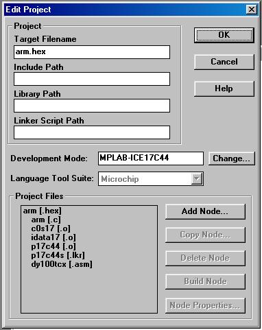
5.3. Select Project->Open Project and select your
robot.pjt file. Whatever windows were up when project was saved will come
up when it is opened.
5.4. Setup the MPLAB system for emulation by selecting Options->Development Mode... Select MPLAB-ICE Emulator in the dialog box and click Reset. The lights on the MPLAB-ICE emulator should flash and the red H light should be eluminated. The system is now reset and ready to 
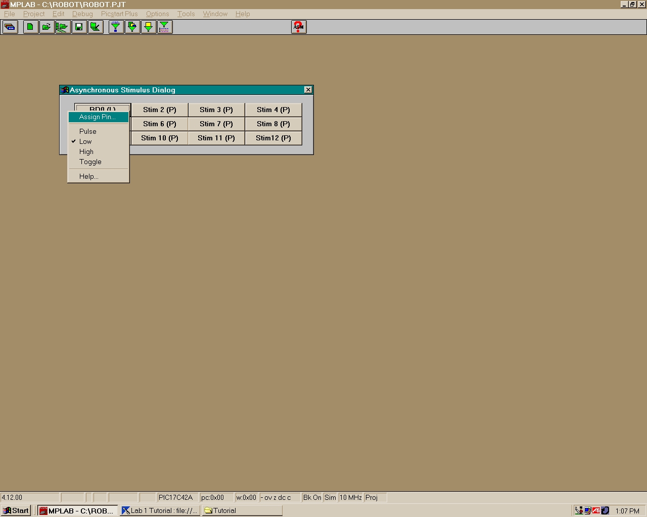
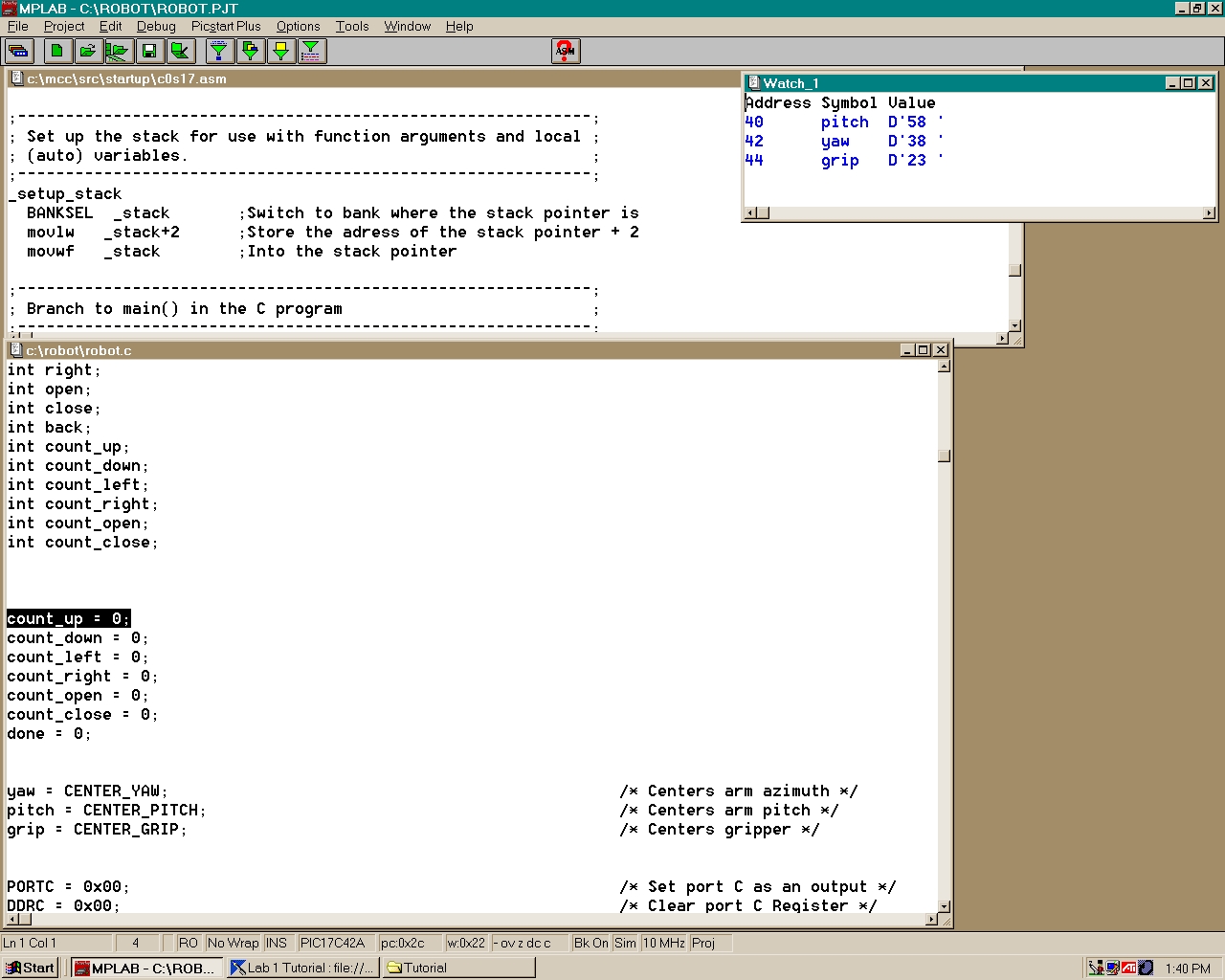
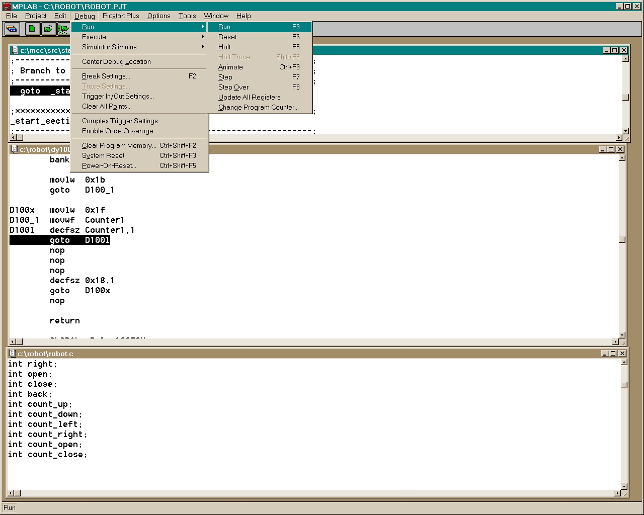
run. Click Debug->Run->Run or push the F9 key to start the program. The robotic arm should move the the center postion for the pitch, yaw and grip. The robotic arm should move in the direction as you push the buttons. It will stop moving in whichever direction if it reaches the limit set in the software or both buttons are pressed simutaneously.
5.5. Connect oscillioscope the signal pins of the servos (yellow wire to the servo wire). View the how the pulse width and postions vary as the robotic arm moves.
6.1. Find the robot.hex file in your directory. Transfer it to the other computer via disk or upload it to the temporary network drive.
6.8. Tab over to Devices/Program. Hit enter and you will be asked if you wish to program this chip. Hit enter again. The chip will be programmed. You will get a failure due to when the chip is programmed it is secured and then cannot be verified.
6.9. The microcontroller is now programmed and ready to be inserted in the test board. Take caution to be properly grounded while handling chip and when inserting chip into board. Apply power to the test board and test functionality. Caution: For some reason the microcontroller chip is very sensitive take care not to touch any part of the chip while power is applied to the circuit.