III. Post-layout Simulation with vasim
Table of Contents
Introduction
In this tutorial we will use Mentor Graphics Pyxis Design Suite and Calibre to simulate the resulting schematic from Tutorial II. Specifically, the transient response of the schematic will be examined to verify the correct operation of the full custom designed inverter.
Parasitic Extraction with Calibre Interactive PEX
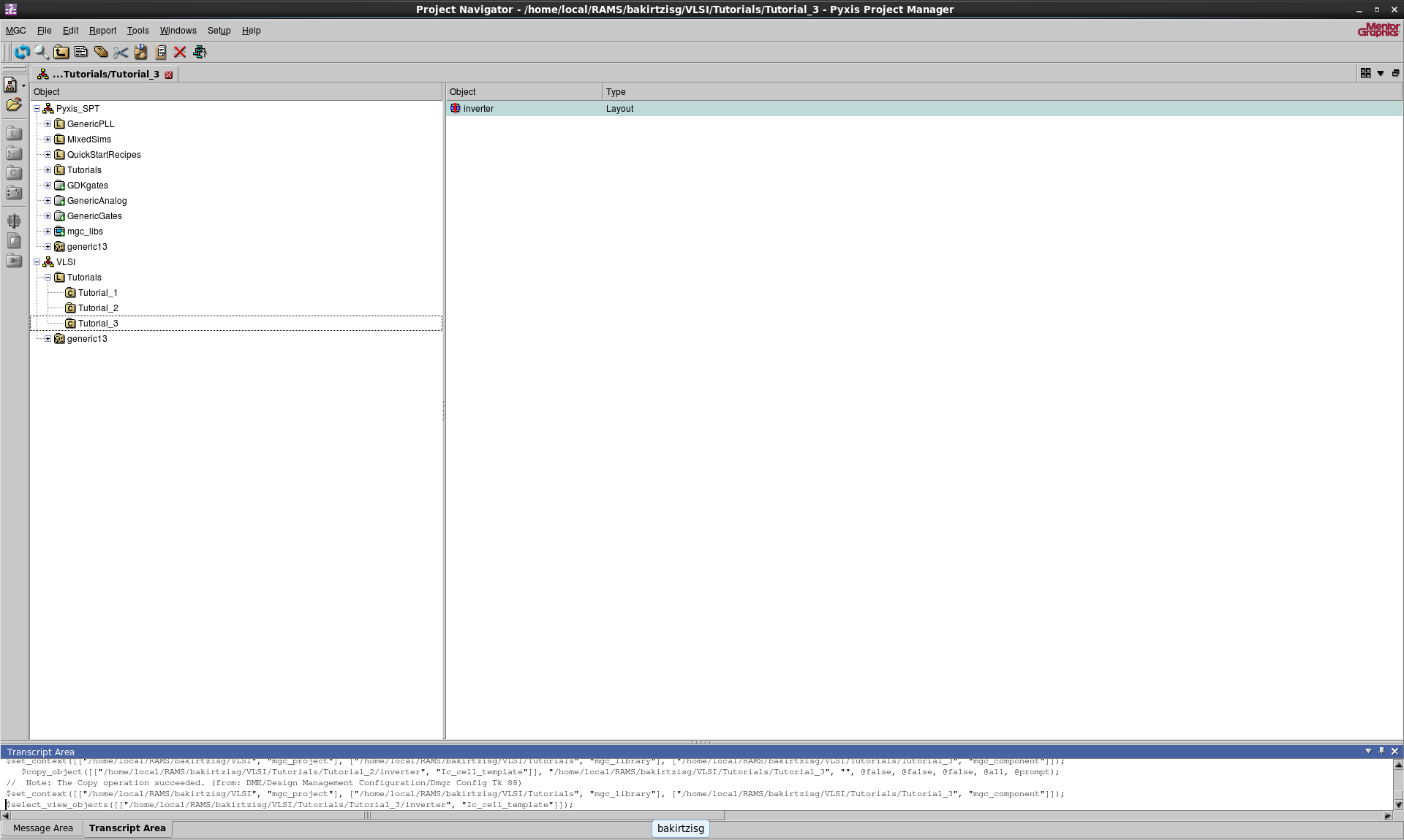
In the Pyxis Project Navigator right click on Tutorials and create a new
cell Tutorial_3. Then copy your inverter layout from Tutorial 2.
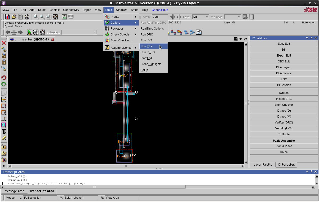
Open the Tutorial_3 inverter in Pyxis Layout navigate to Tools > Calibre > Run PEX
in Pyxis Layout.
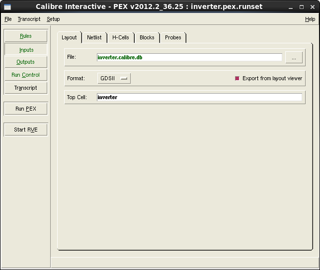
You should now see Calibre Interactive PEX.
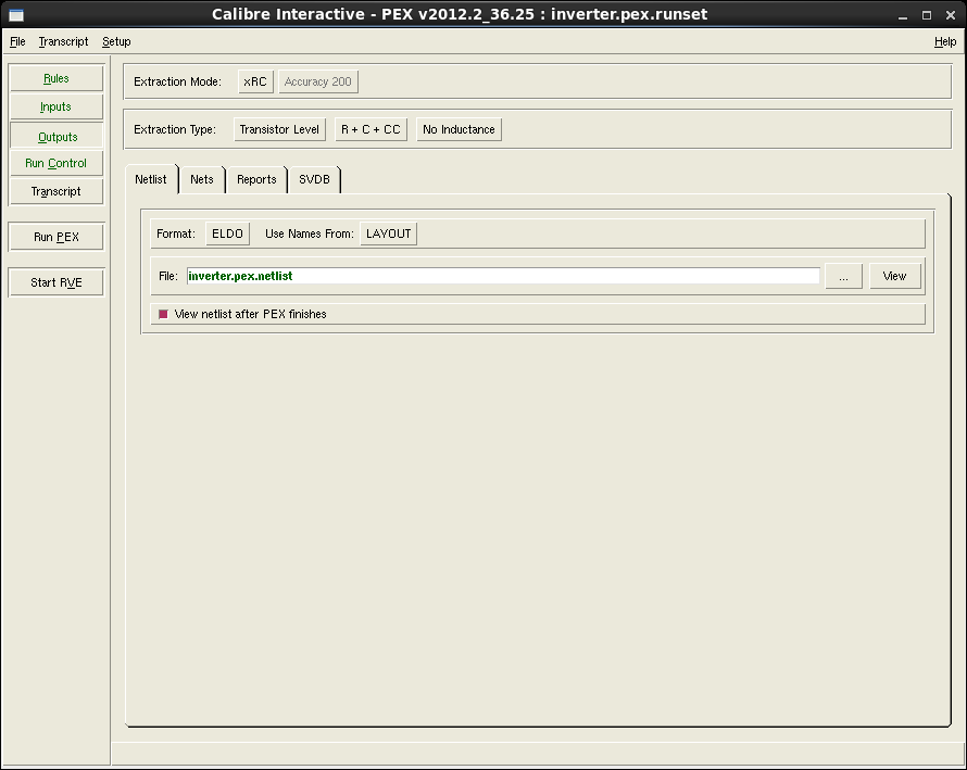
Navigate to Outputs > Netlist. Make sure that the specified format is
ELDO and set the Use Names From to LAYOUT.
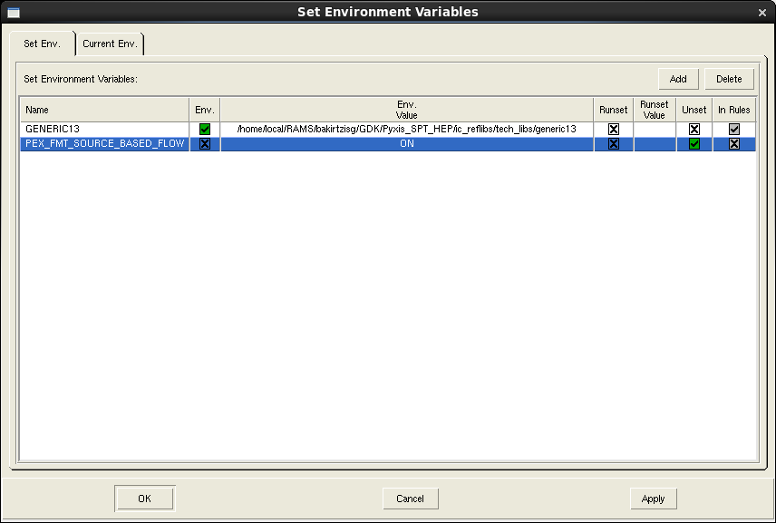
Navigate to Setup > Set Environment. Add an environment variable with
name PEX_FMT_SOURCE_BASED_FLOW. Scroll to the right and select
Unset. Press Apply followed by OK.
Then Run PEX this might take a moment. The SPICE file should have been
successfully created. Close PEX the file will be automatically saved.
Formatting the SPICE File
Open a terminal (Applications > System Tools > Terminal) and set it up for the vasim tools.
$ cd GDK/Pyxis_SPT_HEP
$ . ./setup_vasim
Note that the command above is a ".", a space, and then ./setup_vasim
It is necessary to format the SPICE file correctly before with vasim.
In the terminal window that you setup for vasim, navigate to
Tutorial_3/inverter.cal in your project folder then run cell_sim_prep_vasim on the
inverter cell.
$ cd ~/EGRE533/VLSI/Tutorials/Tutorial_3/inverter.cal
$ $PYXIS_SPT_AREA/cell_sim_prep_vasim inverter
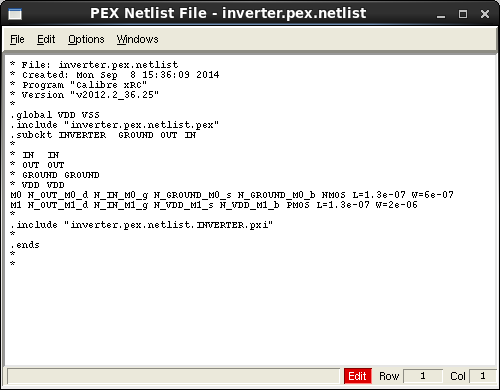
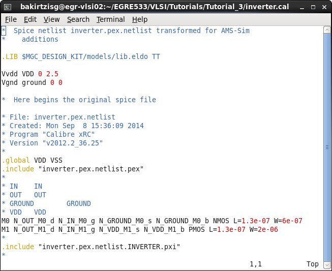
Open the resulting file (e.g., inverter.sp). It should look like the one
below.
The script should have also created a file called inverter.cir. Open that
file as well, it should look like the one below.
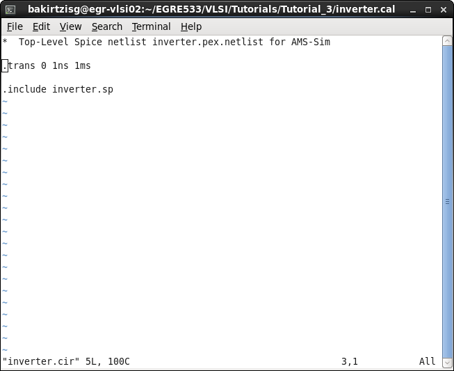
This file specifies the type of analysis that should be run by the simulator – in this case, a transient, or timing analysis. The 1ns parameter is the minimum time step for the simulation and the 1 ms is the maximum time that the simulation can run. If, in simulating larger cells, you need to simulate for longer than 1ms, you will need to edit this file to change this parameter.
Close the text editor.
Simulation of the Model
Navigate back to Tutorial_3, create a work library for vasim, and start
vasim.
$ cd ..
$ valib work
$ vasim
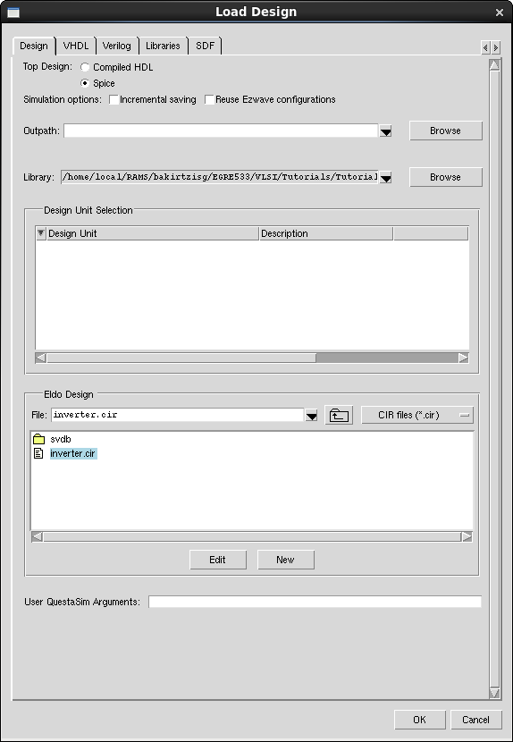
In Load Design change the Top Design to Spice and in inverter.cal
choose inverter.cir. Press OK.
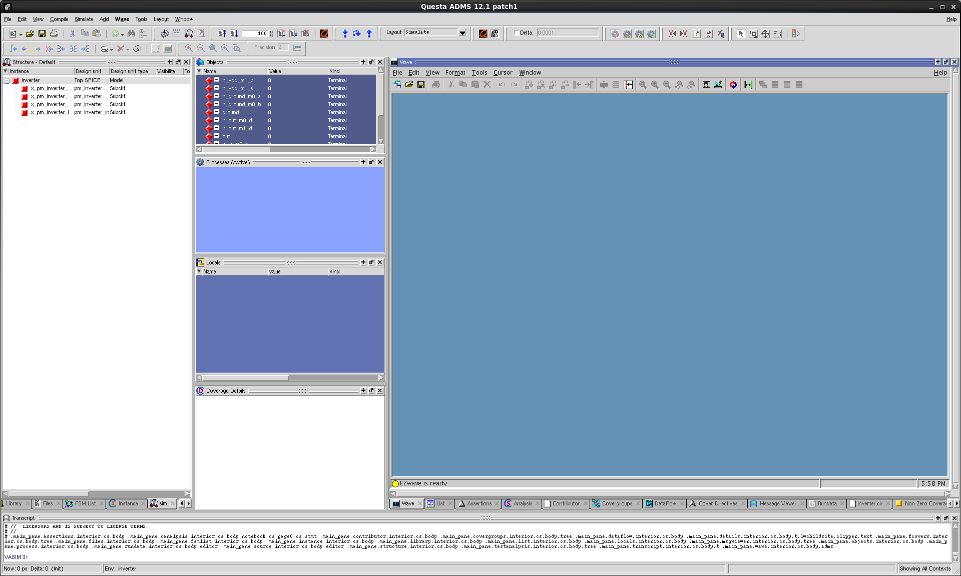
When Load done appears in the transcript of the main vasim window, select
the View > All Windows menu item to bring up all of the
simulator windows. The result should be a set of windows as shown below.
In order to simulate a SPICE cell in vasim, you have to force values on
its inputs – just as you did for the transistor level schematic in
Pyxis. There are several ways to do this in vasim, but one of the best
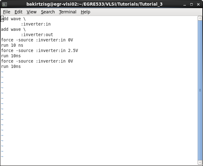
ways is to create a "do file" for the component. A "do file" is simply a
list of simulation commands. In this case, we need commands to trace
signals we want to look at, commands to force values onto input signals,
and run commands to run the simulator.
Use a text editor to create a "do file" like the one below.
To "run" the do file, simply type the do inverter.do in the vasim
transcript window.
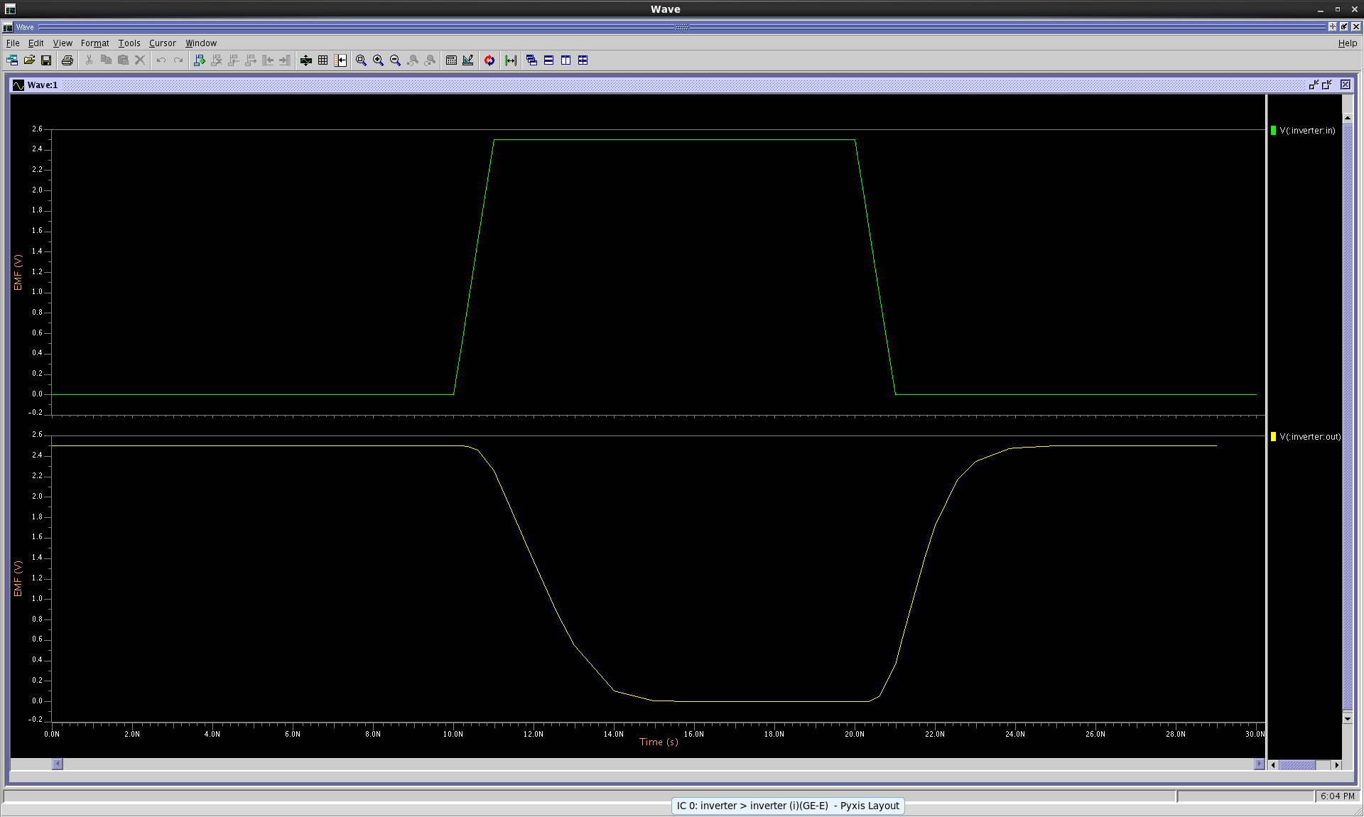
If the simulation finished successfully the waveforms for the input and the
output should appear in the EZwave window.
Exit vasim by typing "quit" in the vasim transcript window.