As mentioned previously, a
do
file is a text file of commands (in the Mentor Graphics scripting language
called AMPLE) that can be used to automate tasks like repetitive simulations
for debugging purposes. The syntax of the AMPLE commands fore each action
you want the tool to do can be looked up in the Mentor documentation, but
a better approach is to simply execute the command once in the actual tool,
and then capture the resulting command from the transcript window into
the do file.
9.1 Using a text editor
(such as xemacs), create a text file, called and_gate.do , that
contains the following commands:
$$open_sheet(["/ : sheet1"],
@noentity, @pop_existing);
$$add_traces(@nooverlay,
void, void, @nomap, "", "in1");
$$add_traces(@nooverlay,
void, void, @nomap, "", "in2");
$$add_traces(@nooverlay,
void, void, @nomap, "", "out1");
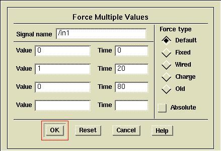
$force("/in1", "0", 0,
void, void, @relative, @norepeat, void);
$force("/in1", "1", 20,
void, void, @relative, @norepeat, void);
$force("/in1", "0", 80,
void, void, @relative, @norepeat, void);
$force("/in2", "0", 0,
void, void, @relative, @norepeat, void);
$force("/in2", "1", 20,
void, void, @relative, @norepeat, void);
$force("/in2", "0", 40,
void, void, @relative, @norepeat, void);
$force("/in2", "1", 60,
void, void, @relative, @norepeat, void);
$force("/in2", "0", 100,
void, void, @relative, @norepeat, void);
$run(120, @relative);
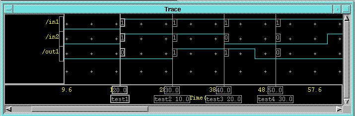
$add_cursor("test1", 20);
$add_cursor("test2", 30);
$add_cursor("test3", 40);
$add_cursor("test4", 50);
$set_active_window("Trace");
$view_all();
Note that most of these commands
should appear in the transcript window from the previous Quicksim
session and can be cut and pasted from there.
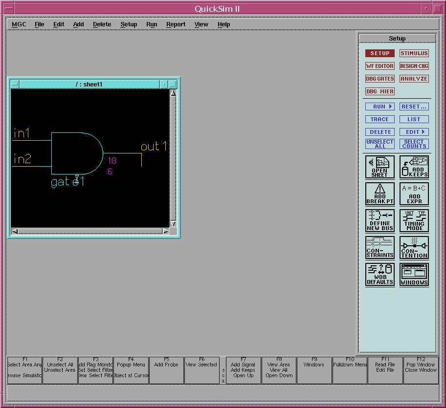
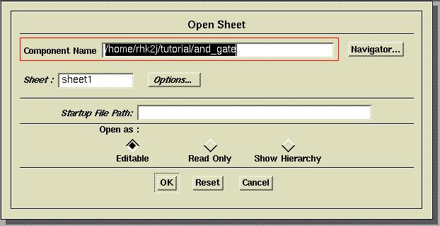
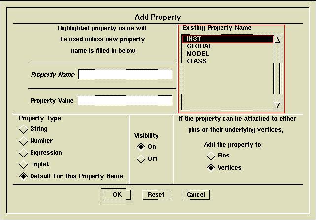
9.2 Start the QuickSim
tool on the and_gate design as before:
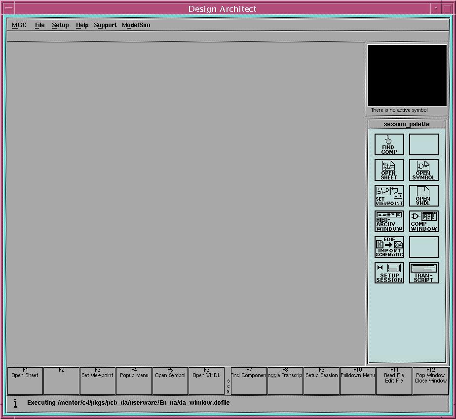
 button on the session_palette
on the right side of the DA window with the left mouse button, or
using the File->Open->Sheet... menu item from the pull-down menus
at the top of the window. Either way, the Open Sheet dialog box,
like the one shown below, should appear:
button on the session_palette
on the right side of the DA window with the left mouse button, or
using the File->Open->Sheet... menu item from the pull-down menus
at the top of the window. Either way, the Open Sheet dialog box,
like the one shown below, should appear: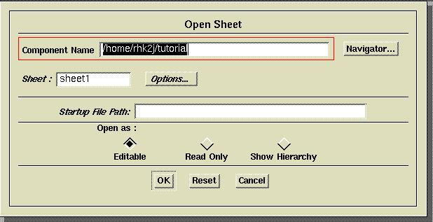

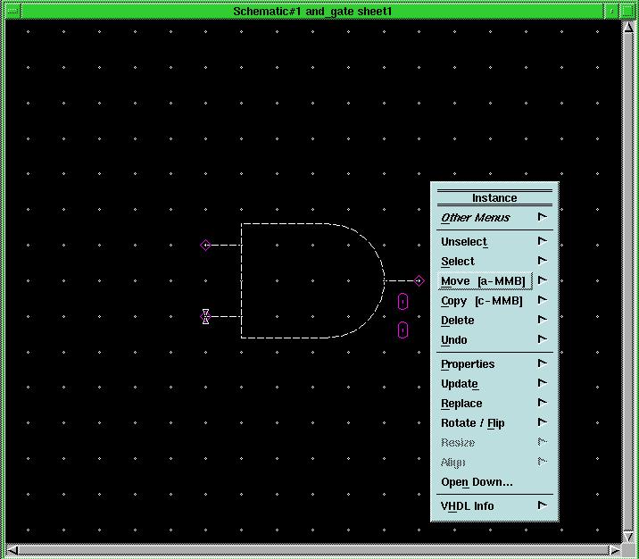
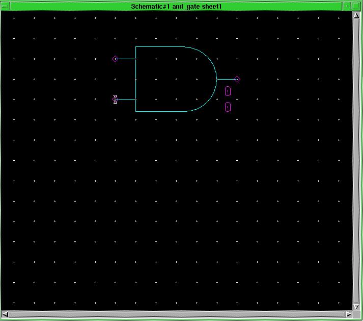
 button. This
will bring up the Add Wire dialog box at the bottom of the DA
window and change the cursor to a cross hair that snaps to grid locations
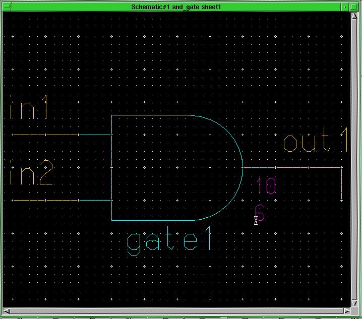
on the schematic window. Place the cursor on the output pin of the and2
component (the small purple diamond) and single click the left mouse button.
Move the cursor two grid spaces to the right and single click again. Move
the cursor down one grid location and double click the mouse button to
end the wire. Notice that a single click of the mouse button adds a "vertex"
or pivot point, to an active wire, and double clicking ends the current
wire. Also notice that when a correct connection has been made to the pin
of a component on the schematic, the purple triangle disappears.
button. This
will bring up the Add Wire dialog box at the bottom of the DA
window and change the cursor to a cross hair that snaps to grid locations
on the schematic window. Place the cursor on the output pin of the and2
component (the small purple diamond) and single click the left mouse button.
Move the cursor two grid spaces to the right and single click again. Move
the cursor down one grid location and double click the mouse button to
end the wire. Notice that a single click of the mouse button adds a "vertex"
or pivot point, to an active wire, and double clicking ends the current
wire. Also notice that when a correct connection has been made to the pin
of a component on the schematic, the purple triangle disappears.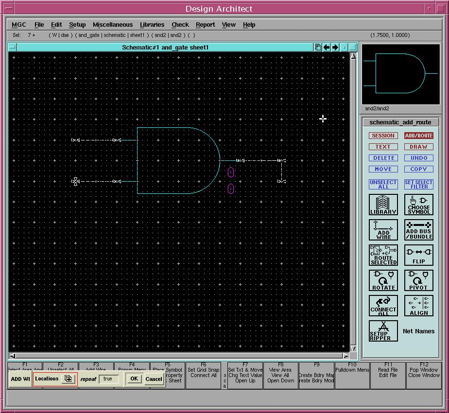
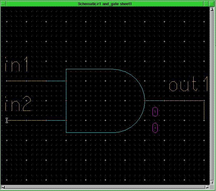
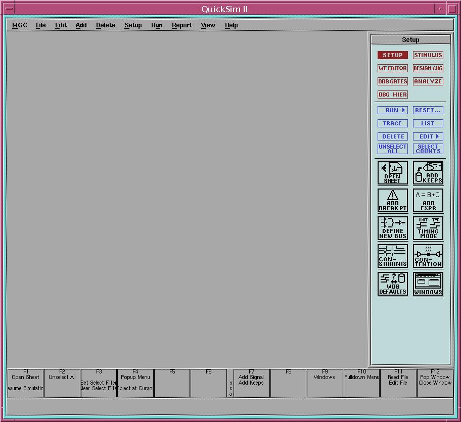
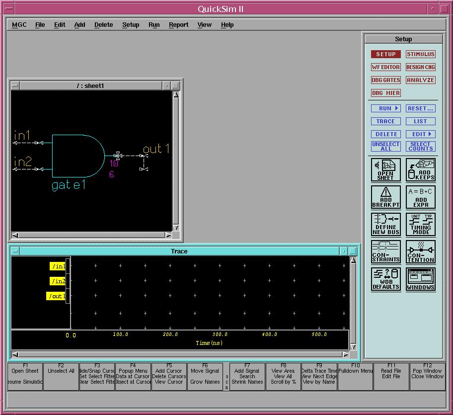
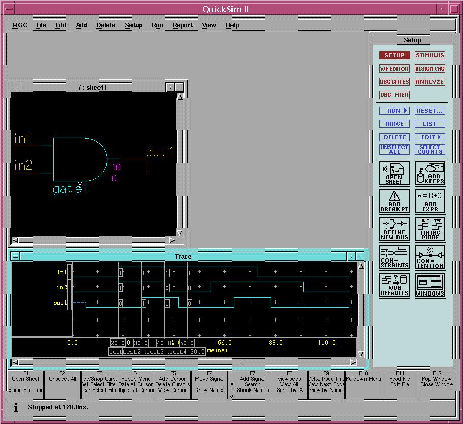
 button to open the schematic sheet. This allows you to select actual signals
on the sheet to add traces, force them to values, etc. The QuickSim
window should now look like this:
button to open the schematic sheet. This allows you to select actual signals
on the sheet to add traces, force them to values, etc. The QuickSim
window should now look like this: