Design for Actel FPGAs using VHDL and Synthesis
1. What you will learn
1.1 How to create and compile a VHDL file for
synthesis.
1.2 How to functionally simulate the VHDL part
alone and on a schematic with other parts.
1.3 How to synthesize a VHDL description targeted
towards Actel primitives.
1.4 How to incorporate the synthesized part
in a schematic with other Actel parts to generate a complete design.
2. Create a behavioral VHDL description of the chip1 design
2.1 If not already there, move back to your
tutorial directory:
>> cd /students/<your_id>/egre427/tutorial
2.2 Open a new VHDL file called adder1.vhd
using your favorite text editor and enter the following VHDL description
into the file:
library IEEE;
use IEEE.std_logic_1164.all;
use IEEE.std_logic_unsigned.all;
ENTITY adder1 is
PORT(a : IN std_logic;
b : IN std_logic;
cin : IN std_logic;
sum : OUT std_logic;
cout : OUT std_logic);
END adder1;
ARCHITECTURE behavior OF adder1 IS
SIGNAL result : std_logic_vector(1 downto
0);
CONSTANT delay : time := 20 ns;
BEGIN
PROCESS(a,b,cin,result)
VARIABLE a_temp : std_logic_vector(1 downto
0) := "00";
VARIABLE b_temp : std_logic_vector(1 downto
0) := "00";
VARIABLE cin_temp : std_logic_vector(1
downto 0) := "00";
BEGIN
a_temp(0) := a;
b_temp(0) := b;
cin_temp(0) := cin;
result <= a_temp + b_temp + cin_temp;
cout <= result(1) AFTER delay;
sum <= result(0) AFTER delay;
END PROCESS;
END behavior;
Note that the IEEE std_logic_1164 and
std_logic_unsigned
packages are used in this description. These packages are supported by
the Leonardo Spectrum synthesis tool. For more details on the VHDL
syntax supported for synthesis, see the Leonardo Spectrum HDL Synthesis
Guide (/mentor/exemplar/doc/hdl_syn.pdf).
2.3 Compile the VHDL file. Note that later,
this VHDL model will be simulated with other Actel parts models using the
QHPro
tool, so the -qspro_syminfo switch will be used now to generate
the necessary information:
>>vlib work
>>vmap work ./work
>>vcom -qspro_syminfo
adder1.vhd
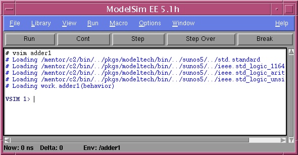
You should see the following lines printed out with no
errors:
// ModelSim EE/VHDL 5.1h Oct 1 1998
SunOS 5.6
//
// Copyright (c) Mentor Graphics Corporation, 1982-1998,
All Rights Reserved.
//
UNPUBLISHED, LICENSED SOFTWARE.
//
CONFIDENTIAL AND PROPRIETARY INFORMATION WHICH IS THE
//
PROPERTY OF MENTOR GRAPHICS CORPORATION OR ITS LICENSORS.
//
// Copyright (c) Model Technology Incorporated
1990-1998, All Rights Reserved.
//
-- Loading package standard
-- Loading package std_logic_1164
-- Loading package std_logic_arith
-- Loading package std_logic_unsigned
-- Compiling entity adder1
-- Compiling architecture behavior of adder1
3. Simulate the VHDL model by itself
The VHDL model should be functionally simulated by itself
to ensure correct operation before it is added to a larger system.
3.1 Invoke the ModelSim simulator
on the
adder1 design:
3.2 You should see a display like the one below:
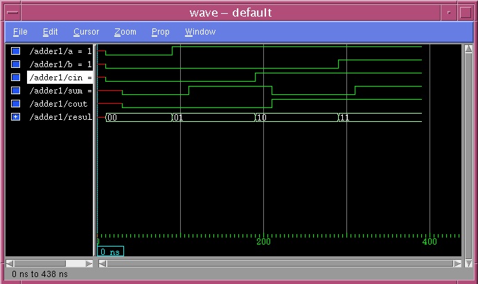
3.3 Use the View->Signals... menu item
to bring up the Signals display. Use the Wave->Signals in design
menu item in the Signals window to create a Wave window.
Finally, force values on each of the input signals using the Force...
menu item in the Signals window and run the simulation using the
Run->100ns
menu item in the main window. The resulting Wave window should look
like this:
3.4 Exit the QuickHDL simulator using
the
File->Quit menu item in the main window.
4. Generate a symbol for the VHDL model
In order to incorporate the VHDL model into a large system
for functional simulation, a symbol, with the necessary properties for
QSPro
on it, must be created.
4.1 Invoke Design Architect :
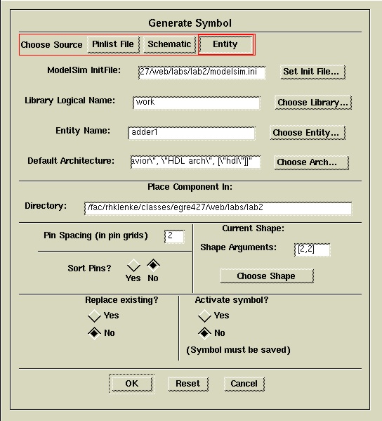
4.2 Use the File->Generate->Symbol... menu item
to bring up the Generate Symbol dialog box. Click on the Entity
button at the top of the dialog box. Click on the Set Init File...button
and select the modelsim.ini file in the Set ModelSim init file
dialog box and click OK. Click on the Choose Library... button
and select ["work", "./work"] and click OK in the
Choose
HDL Library dialog box that pops up. Click on the Choose Entity...
button and select adder1 and click OK in the
Choose Entity
dialog box that pops up. Finally, click on the Choose Arch... button
and select [\"behavior\", \"HDL arch\", [\"hdl\"]] and click OK
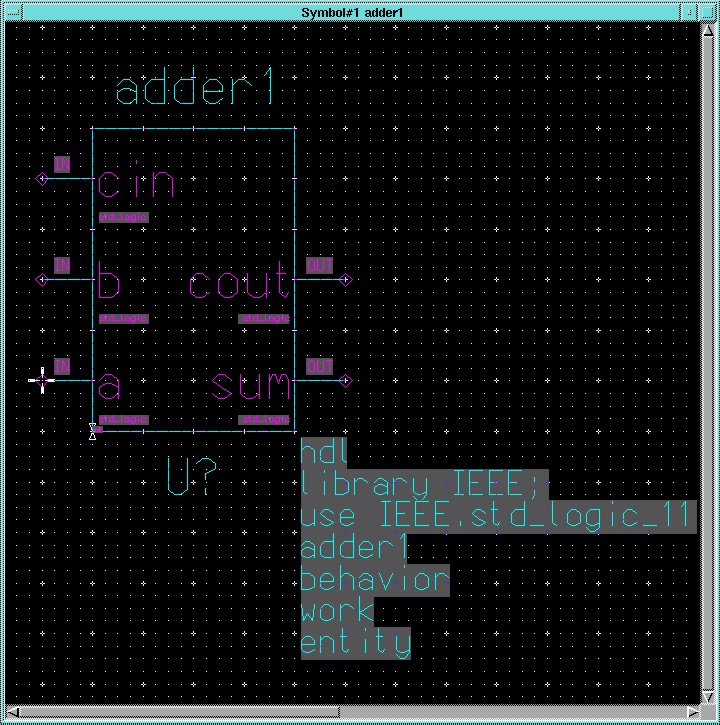
in the Choose Architecture dialog box that pops up. The result should
be a Generate Symbol dialog box that is filled out like the one
below. Click OK in the Generate Symbol dialog box.
Note that a symbol window will pop up with the
adder1
symbol in it. The symbol will have the proper input and output ports added
to it and will also have some properties for the QSPro tool on it.
It is important to not delete or change these properties in any way to
avoid disrupting the function of QSPro . If these properties should
ever become corrupted, the best course of action is to generate a new symbol
from the VHDL source as above.
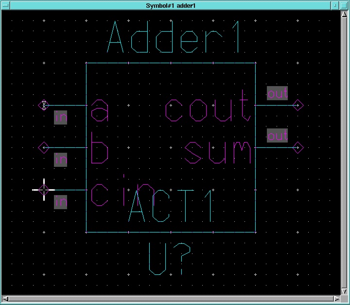
4.3 As you have done before, it is a good idea
to add inst and comp properties to the symbol. Select the
symbol body and use the Properties->Add->Add Single Property...
item from the pop up menu to add these properties. The resulting symbol
should look like the one below.
4.4 Check and Save the symbol
and close the Symbol window.
5. Create a 4 bit adder system that uses both the Actel full adder designed
in Lab 1 and the VHDL adder created above
5.1 With DA still open, use the Open
Sheet button to open a sheet called "adder4." Use the Choose Symbol
button to select the full_adder component symbol from lab 1. Instantiate
two of these adders on the sheet.
5.2 Use the Choose Symbol button again
to select the adder1 component created above. Instantiate two of
these components.
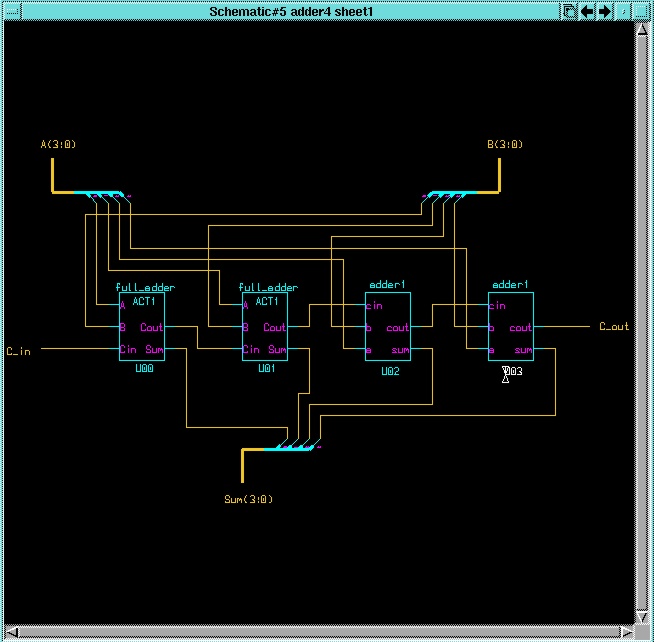
5.3 Connect the four single bit adders in ripple
carry configuration to implement a 4 bit adder. Add busses for the A
and B inputs and the Sum output. Add a carry in and carry
out signal. Note that since this schematic will be used for functional
simulation only, it is not necessary to add Actel I/O pads or even portins
and portouts for the system's inputs and outputs. Be sure to change
the inst properties on each adder to some unique value. The resulting
schematic should look like this:
6. Simulate the 4 bit adder with QHPro
The entire system, consisting of VHDL models and Actel
parts, will now be simulated. Be sure to run the presimvpt tool
on the adder4 design first to generate a viewpoint for the Actel parts.
6.1 Run presimvpt :
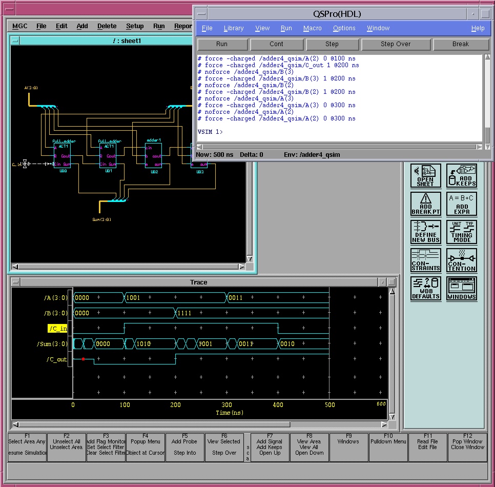
6.2 Start-up the QSPro tool on the adder4
design:
Note that both the Quicksim and QuickHDL
simulator user interfaces appear. However, it is possible to trace all
of the signals in the design and control the simulation from within the
Quicksim window only. Use the Solver->Quicksim menu item within
the Quicksim window to setup simulation to be controlled from the
Quicksim
window.
6.3 Use the Open Sheet button to open
the schematic. Add traces for the input and output signals and force values
on the inputs. Run the simulation for the proper amount of time recalling
that there are delays added to the VHDL models and that this is a ripple
carry implementation. The resulting window should look similar to the one
below.
7. Synthesize the VHDL models to Actel parts
After the VHDL model is synthesized, a new symbol (and
optionally a schematic) will be generated for it. If the part is synthesized
in the same directory as the VHDL description, the new symbol will overwrite
the old one, making it difficult to go back and resimulate the VHDL model
if it is necessary to change it. To avoid this problem, it is best to synthesize
the VHDL model in a different directory.
7.2 Create a directory called "actel" (the name
isn't important) to hold the synthesized parts:
Now it is possible to copy the VHDL source file into
this directory, but then if changes are necessary, keeping both copies
updated to the latest version can be a problem. Therefore, it is better
to create a Unix link to the original source code in this directory.
That way, only one copy of the source code exists and version control is
not a problem:
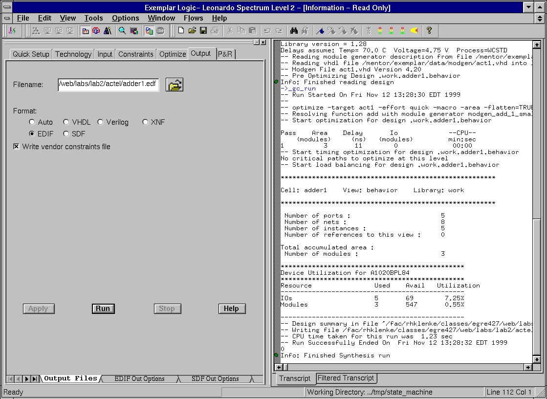
7.3 Invoke the Exemplar Leonardo synthesis
tool:
A Leonardo Spectrum window like the one below
should appear.
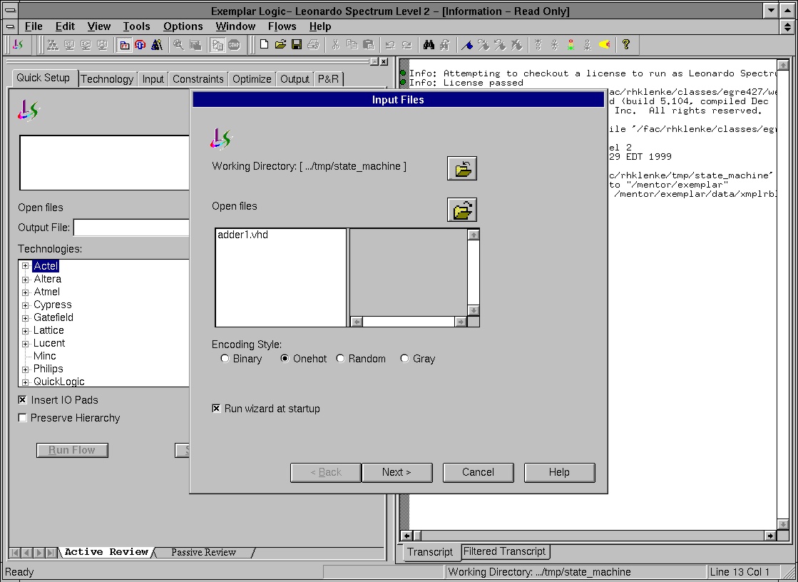
7.4 Click off the
Run Wizard at Startup
button in the
INPUT FILES box and click
Cancel. In the main
window, click on the

button in the
Quick Setup tab and select the
adder1.vhd
file. Select
Actel ACT1 in the
Device box and select the
A1020BPL84
part. Click off the
Insert I/O Pads button. Select the
Technology
tab and set
Max Fanout to 14. Select the
Outout tap and make
set the
Format to EDIF. Click the
Run button. When the run
is finished, the window should look like the one below:
Note that only a simple area optimization was done during
the synthesis process. If more complex optimizations, including optimizations
for speed, are desired, consult the Leonardo Spectrum User's Guide
for details (/mentor/exemplar/leo_user.pdf).
7.5 Exit Leonardo by using the File->Exit
menu item in the Leonardo Spectrum window.
8. Import the design back into the Mentor environment and generate a symbol
for it
The Actel edn2mgc command reads in the EDIF file
created by Leonardo and creates a Mentor Graphics database for the
design. The database is placed under a new directory called "work."
8.1 Invoke the edn2mgc tool on the adder1.edf
file generated by Galileo :
Invoke DA to generate a symbol for the
synthesized part:
8.2 Click on the Open Symbol button and use the
Navigator...
button in the Open Symbol dialog box to go into the "work" directory
and select the adder1 component. Click
OK in the Open
Symbol dialog box.
8.3 A symbol window will open and a symbol for the synthesized
adder1
part will be created within it. Use the Properties->Add->Add Single
Property... item from the pop up menus to add the als_technology
property with the value of ACT1 and the comp and inst
properties as before. Also, wiring the symbol to the sheet will be easier
if you flip the order of the a,b, and cin
inputs on the symbol. The resulting symbol should look like the one below.
8.4 Check and Save the symbol and exit
DA .
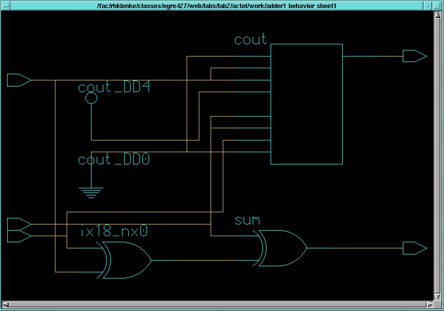
9. Generate a schematic for the synthesized design
Invoke the Mentor Graphics schematic generator
(sg) tool:
>>sg &
9.1 Use the
File->Open Design from Viewpoint...
menu item to bring up the
Open Design from Viewpoint dialog box.
Click on the
Navigator... button and go into the "work" directory
and into the
adder1 component. Select the
adder1 component
with the

folder next to it and click
OK
in the
Open Design from Viewpoint dialog box. A blank schematic
window will appear in the
sg tool window.
9.2 Use the Setup->Symbol->Use Genlib Classification
menu item to setup the symbol classifications and then use the Partition
Setup... command from the pop up menus (right mouse button) to bring
up the Partition Setup dialog box. Click on the Number of Sheets
button, make sure the Number of Sheets item is set to 1 and click
OK
. Use the Generate item from the pop up menus to generate a schematic
like the one below:
9.3 Use the File->Save menu item to save the schematic
and exit the sg tool.
10. Create a schematic for the 4 bit adder that uses the synthesized parts
The simplest way to generate a schematic for the 4 bit
adder using the synthesized parts is to start with the schematic of the
system with the VHDL models. However, it is a good idea to save that schematic
in case it is necessary to go back and make modifications to the VHDL models.
10.1 Change back to the tutorial directory and
start
DA :
10.2 Use the Open Sheet button to open
the
adder4 sheet. Use the File->Save Sheet As... menu item
to bring up the
Save Sheet As dialog box. Type in "adder4_chip"
in the Component Name box and click OK . Close the adder4
sheet.
10.3 Use the Open Sheet button to open
the
adder4_chip sheet. Delete the old adder1 components from
the sheet. Use the
Choose Symbol button and the navigator to go
into the actel and then the work directories and select the
new, synthesized adder1 symbol. Place two instances on the sheet.
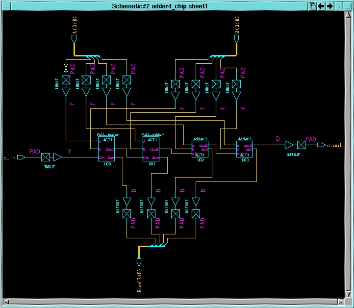
10.4 Reconnect the signals properly and add
Actel I/O pads and portins and portouts to the inputs and
outputs to create a complete Actel design that can be placed and routed.
The resulting schematic should look like this one:
10.5 Check and Save the sheet.
10.6 Use the Miscellaneous->Generate Symbol...
menu item to generate a symbol for the adder4_chip . Add the als_technology
, comp , and inst properties as before. Check and
Save
the symbol and exit the symbol window. Use Check->Schematic in the
schematic window to check the correspondence of the schematic sheet and
symbol. Close the schematic window and exit DA .
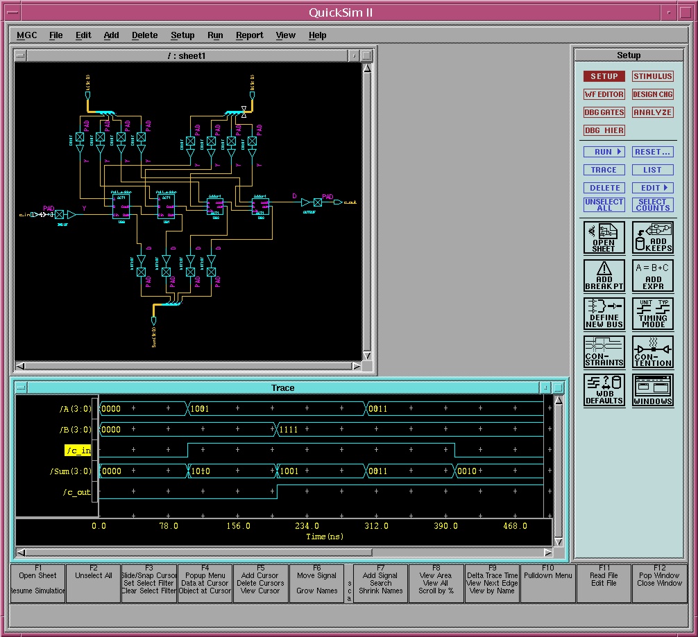
11. Functionally simulate the complete Actel design
The full design, with I/O pads, should be functionally
simulated once more before placement and routing. Note that since all components
are now comprised of Actel parts, it is not necessary to use QHPro
to simulate it - Quicksim will suffice.
11.1 Run the presimvpt tool to prepare
a simulation viewpoint for the Actel parts:
11.2 Invoke Quicksim on the adder4_chip
design:
11.3 Open the sheet and trace all of the input and output
signals. Force values on the inputs and run the simulation. The results
should be similar to those below:
11.4 At this point, the design can be placed and routed
using the Actel tools and simulated with full timing delays just as the
design from the previous tutorial was.