Before creating your first new part type, you will need to setup a user
library. This library will be saved to your network shared drive,
allowing you to access it from any computer in the VCU School of
Engineering.
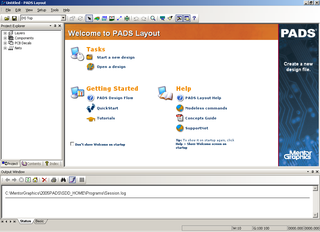
1.1 Start PADS Layout. Select
Start > Programs
> Mentor Graphics SDD > PADS2005 SP2 > PCB Layout > PADS
Layout. The PADS Layout welcome screen should appear.
1.2 Open the Library Manager. Select
File > Library...
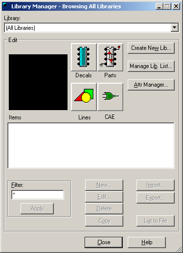
1.3 Press the
Create New Lib...
button. Browse to the
H: Drive and
create a new folder named
Pads Library.
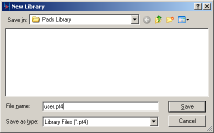
Open this folder and type
user.pt4 in
the file name field. Then press the Save button.
1.4 Once you have created the new library, close the
library manager.
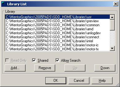
Note: To access this library in future windows sessions: open the
library manager and press the
Manage Lib List...
button. Then press
Add...,
browse to
H:\Pads
Library and select the
user.pt4
file.
We will now create a PCB footprint for the National Semiconductor
LM2675M-3.3 voltage regulator chip. The relevant datasheet can be
found
here.
(Page 24 contains information on the part's physical dimensions).
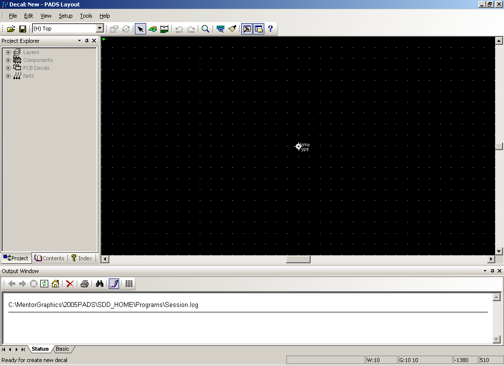
2.1 Open the PCB Decal Editor. In PADS Layout, select
Tools > PCB
Decal Editor. The PADS Layout window should now look
similar to the image below.
2.2 Start the PCB Decal Wizard. Enable the Drafting
Toolbar by pressing the

button.
From the Drafting Toolbar press the Wizard button:

. The Pin
Wizards window will now appear.
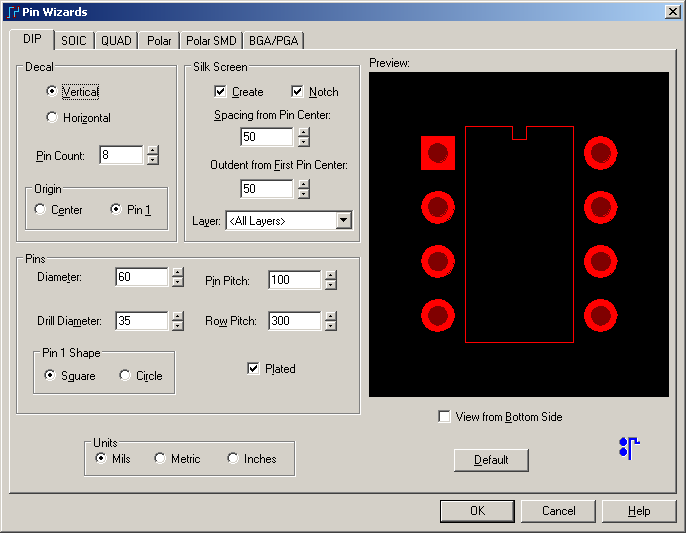
2.3 We will be creating a decal for the 8-pin Small Outline
Package, so select the SOIC tab.
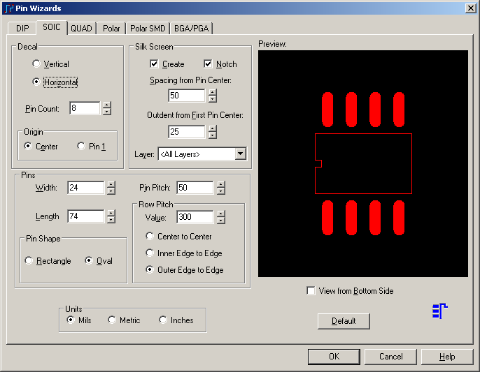
2.4 Make the following changes:
In the Decal area, select Horizontal
and type 8 in the Pin Count box.
In the Silk Screen area, type 55 in the Spacing from Pin Center box.
In the Pins area, type 24 in the Width box, 90 in the Length box and 50
in the Pin Pitch box.
In the Pin Shape area, choose Rectangle.
In the Row Pitch area, type 200 in the Value box, and select Center to
Center.
2.5 When the Pin Wizards window looks like the one
above, press OK. You will now return to the PCB Decal Editor
which should look like the image below.

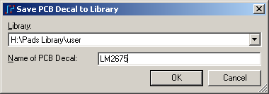
2.6 Save the PCB footprint to your user library.
Select
File
> Save Decal. In the Save PCB Decal to Library dialog,
select
H:\Pads
Library\user for the library and type
LM2675 in
the Name of PCB Decal field.
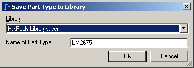
2.7 Press OK. When it asks if you want to create a
new Part Type, say yes, then press OK in the Save Part Type to Library
dialog box.
2.8 Exit the PCB Decal Editor and PADS Layout.
Select
File
> Exit Decal Editor to return to PADS Layout. Then
select
File
> Exit to close PADS Layout.
3.2 Add your user library to the Library List. Select
File >
Library...
Then press the
Manage
Lib List... button.
Press
Add...,
browse to
H:\Pads
Library and select
user.pt4.
After adding your user library, press OK and then close the library
manager.
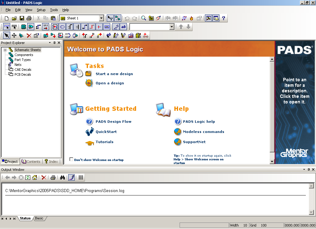
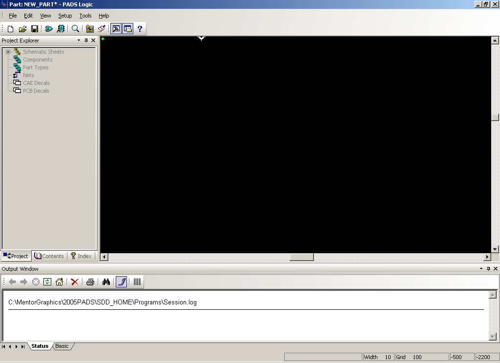
3.3 Open the Part Editor. Select
Tools > Part
Editor. The PADS Logic window should now look similar to
the image below.
3.4 Open the LM2675 part type that you created in part 2 of
this tutorial. Select
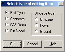
File > Open...
On the Select type of editing item dialog, choose Part Type and press
OK.
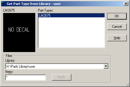
The Get Part Type from Library dialog will appear. In the filter
area, select the
H:\Pads Library\user
library and type
* in the
items box. Press Apply. Now select LM2675 from the
Part-Types list and press OK.
3.5 Edit the part's electrical properties. Press
the

button on the
toolbar to open the Part Information window.
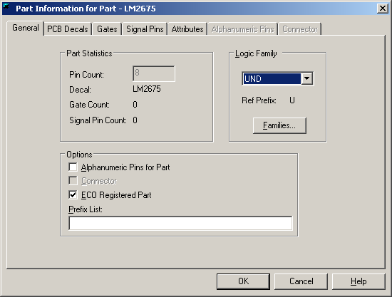
Under Logic Family, select ANA.
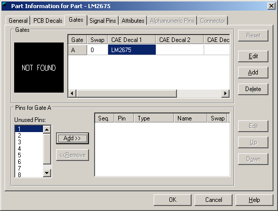
3.6 Specify the (not yet created) schematic decal.
Select the Gates tab.
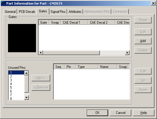
Press the Add button. Click in the CAE Decal 1 field, type LM2675
and press Enter. Then press the OK button.
3.7 Open the CAE Decal Editor. Press the

button on the
toolbar to open the CAE Decal Editor. The Select Gate Decal
dialog will pop up.
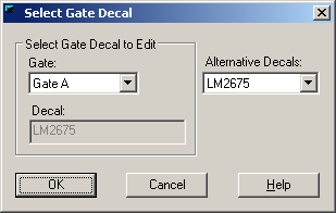
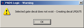
Press OK to continue. PADS Logic will display a warning stating
that the selected decal doesn't exist and will be created. Press
OK.
The CAE Decal Editor should now appear.
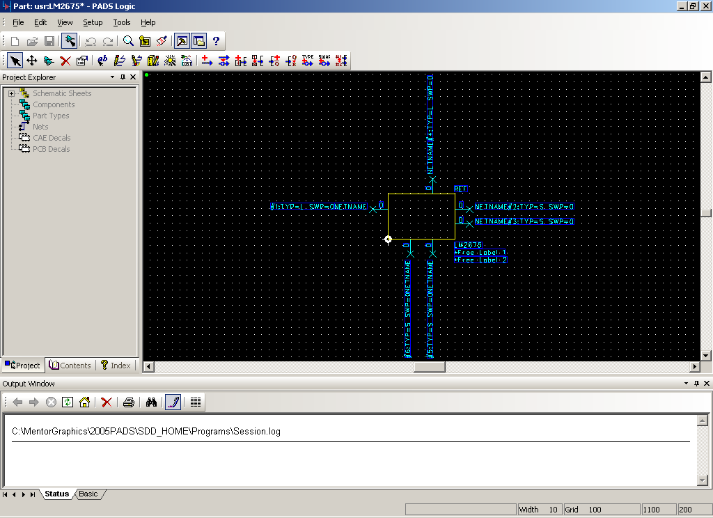
3.8 Start the CAE Decal Wizard. Press the

button on the
Decal Editing toolbar to launch the Decal Wizard.
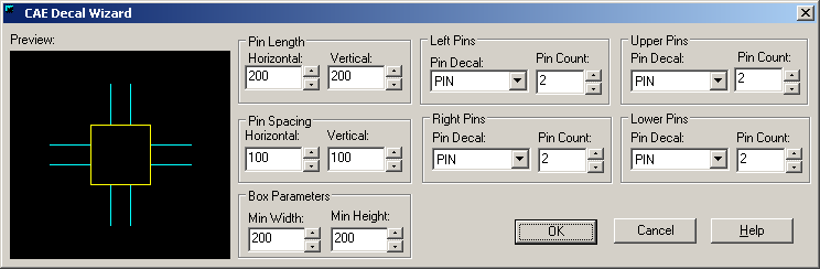
3.9 Make the following changes:
In the Pin Spacing area, type 300 in
the Horizontal box and 200 in the Vertical box.
In the Left Pins area and Upper Pins area, set the Pin Count to 1.
In the Right Pins area and Lower Pins area, set the Pin Count to 2.

When the specified values have been entered, press OK. The CAE
Decal window should now look similar to the one below.
Note: You may wish to zoom in on the decal while making changes to the
pins. To enter zoom mode, press
Ctrl + W.
Use the left mouse button to zoom in and the right mouse button to zoom
out. Press Esc to exit zoom mode.
3.10 Name and Number the pins. Right-click in an
empty area and select the
Select Terminals
menu item. Double click on the leftmost pin. The Terminal
properties dialog will open.
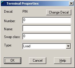
Type 7 in the number box and type VIN in the Name box. Then press
OK. Repeat this process for the remaining 5 pins.
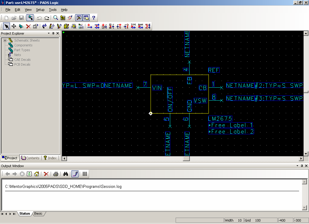
Proceeding clockwise, name and number the pins as follows:
Number: 4, Name: FB
Number: 1, Name: CB
Number: 8, Name: VSW
Number: 6, Name: GND
Number: 5, Name: ON/\OFF
Note: For pin 5, the name will appear as

. The
back-slash is used to specify a logical not and will make a bar appear
over the word immediately following it.
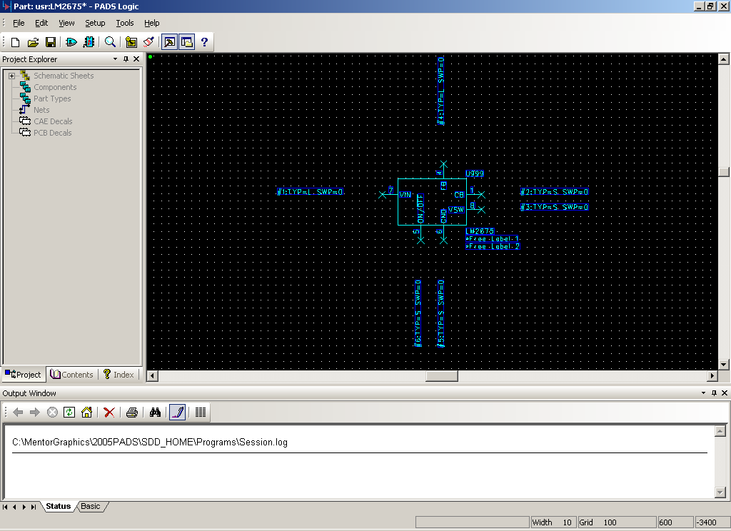
When you are finished naming and numbering the pins, the CAE Decal
Editor should look similar to the image below.
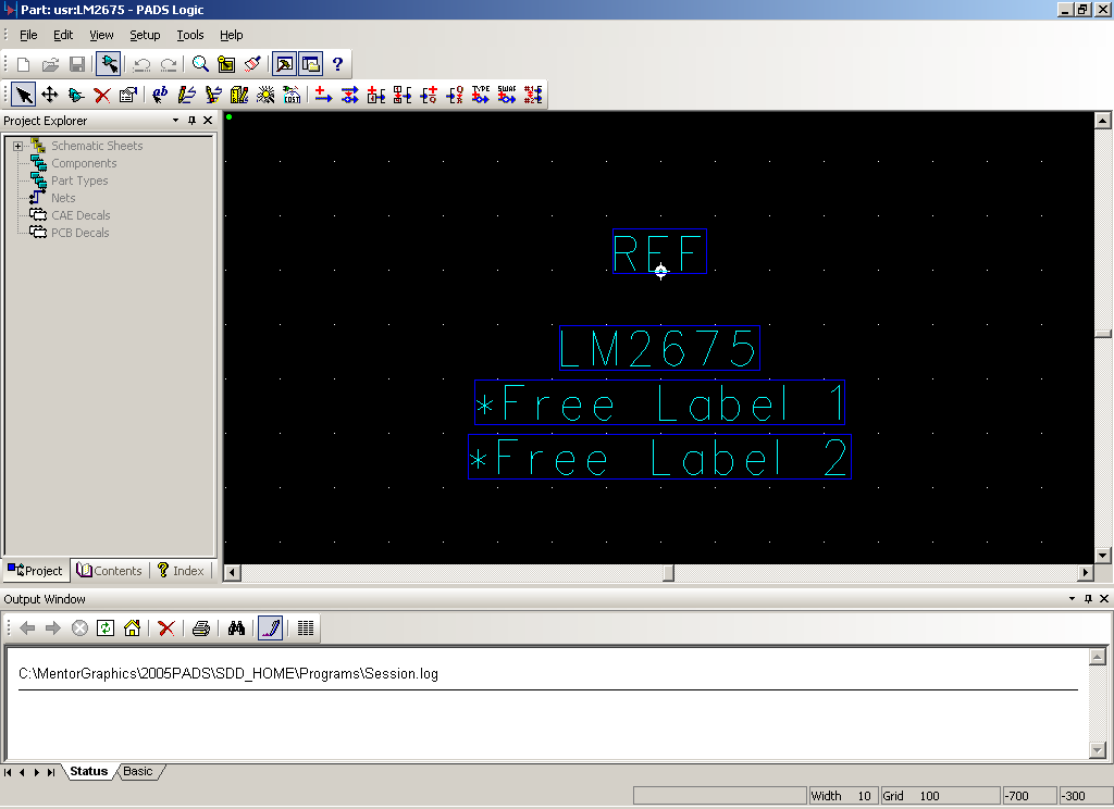
3.11 Save the schematic symbol. Select
File > Return to
Part. When prompted to keep changes, press Yes. The
Part Editor should now look like this:
Select
File
> Save. Then Select
File > Exit Part
Editor.