I'd been putting it off as I didn't really want to get into the hassle of ducted fans and the turbines were too expensive. Then a friend of mine in our club, Capt. Scott "Snack" Strimple finally got his HotSpot with a JetCat P-120 going. I saw it fly and it was great. It looked, sounded, smelled, and flew like a real jet, and operation (well taking off anyway) from a short grass field was NOT a problem.
Luckily, Scott was also a DEALER for JetCat and Planes Plus and got me a deal on a P-80, Kangaroo, and all the associated goodies (how CONVENIENT!). I got permission from the Klenke family CFO (I may be in Europe for a few weeks next summer - quid pro quo), and, thanks to a lot of help and encouragement from Scott, I was off and running as a certified jet jock! The 'Roo has been a challenge, a great, durable learning plane, and is fun to fly, but I'm really a scale nut, so it was only a matter of time before the Panther came up again.
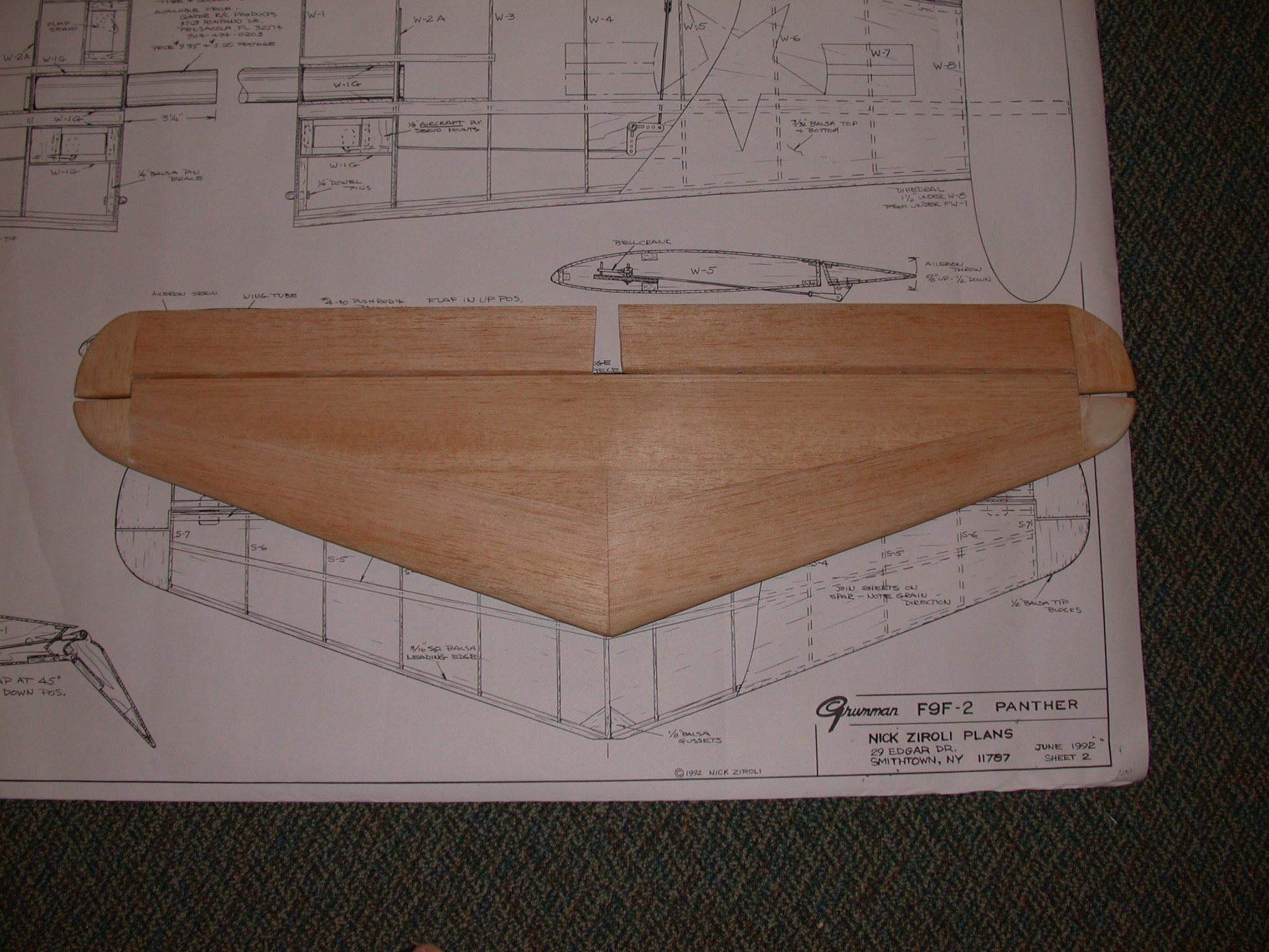
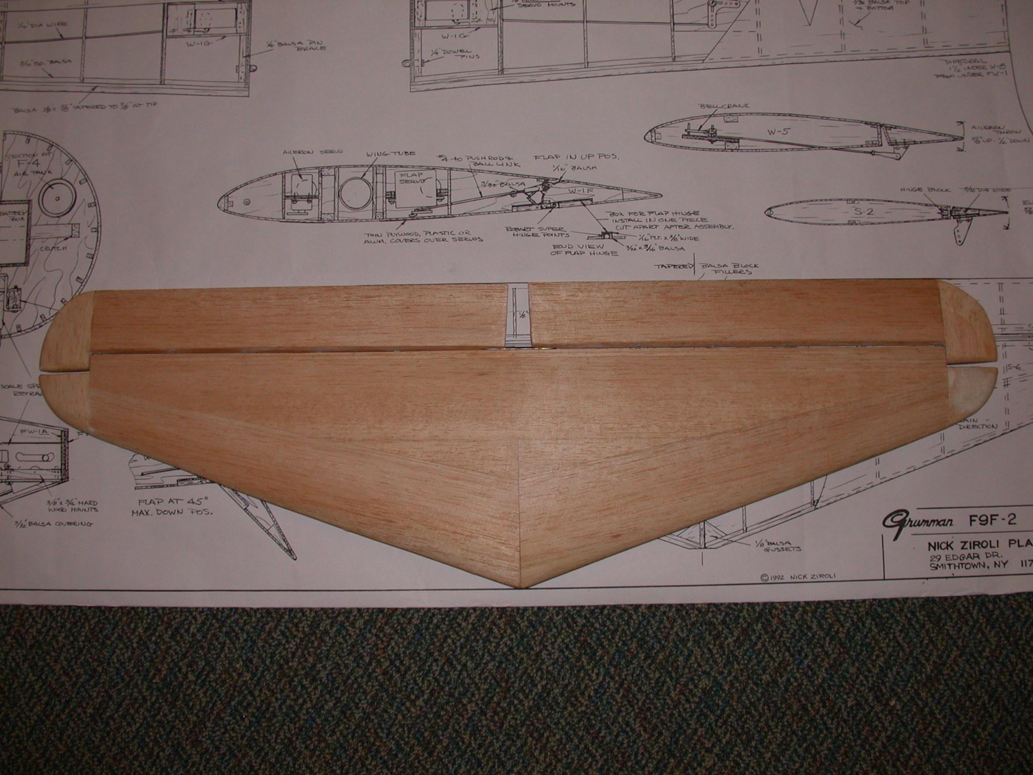
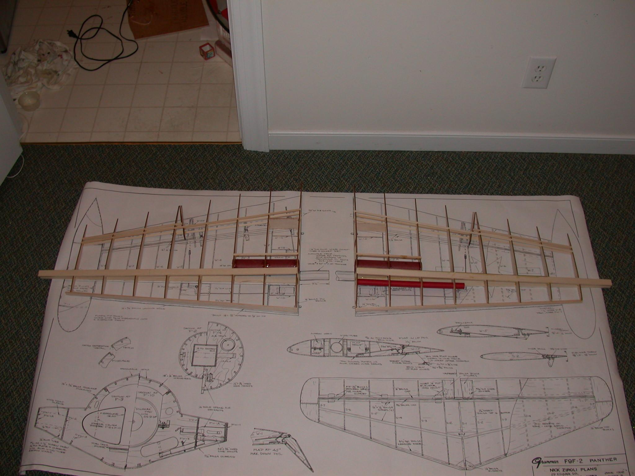
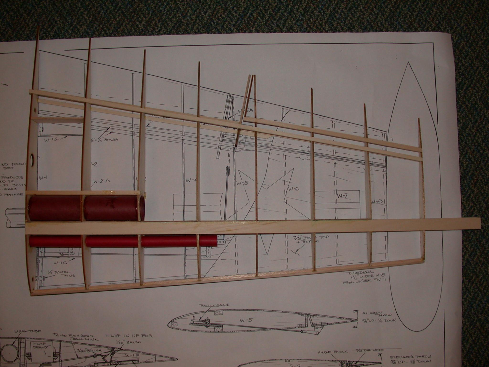
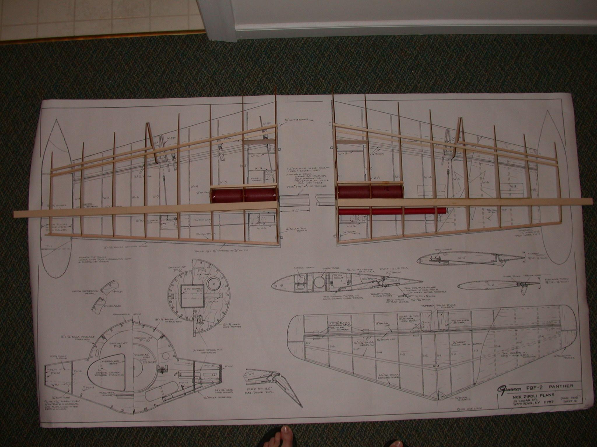
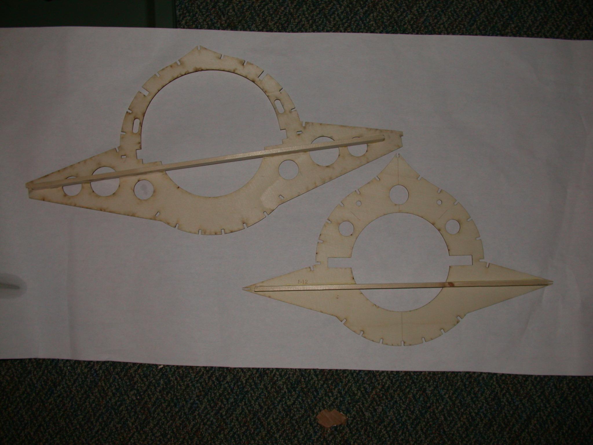
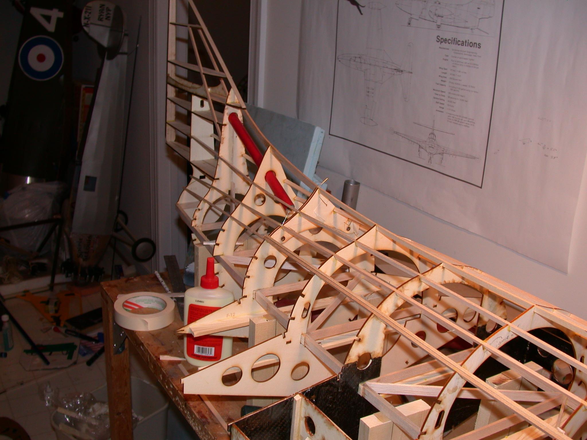
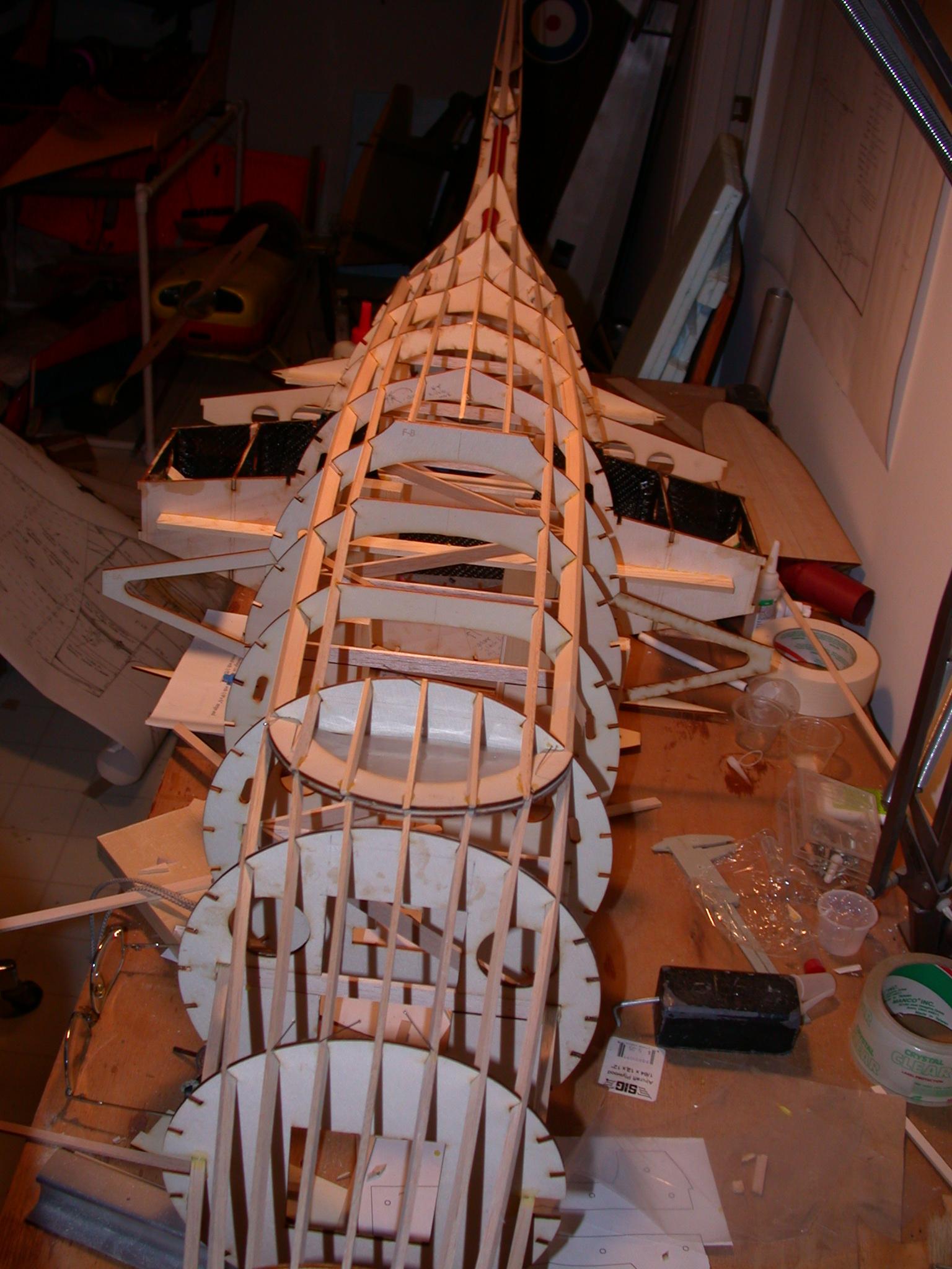
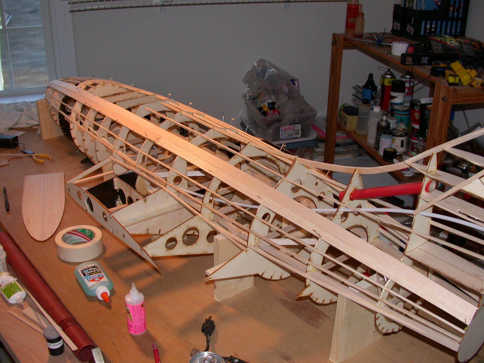
I was reading RC Universe one day and came across a thread on building Panthers. Apparently Joe Huntley had digitized the Ziroli Panther parts templates and a fellow named Jesse at Laser Works in Texas was cutting the parts for a great price. In that thread was a response from a gentleman named Reuben Saliba from Malta, who had built a Ziroli Panther from wood and installed a turbine. I emailed Reuben and my subsequent detailed conversations with him via email (thanks Reuben!) convinced me that the Panther would be a good platform for a turbine. In one of his emails, Reuben mentioned that if he were to build the Panther again, he would blow it up by 15%. Also, in a previous phone conversation, Jesse mentioned that he was reducing the Panther parts by 80% for a customer who wanted to build an EDF version. A quick call to Jesse confirmed that he could easily enlarge the parts by 10% or 15% (although the notch sizes would also change, but that would be easy to deal with). I also called Robart to check and see if they could fit slightly longer struts to the Panther gear set they offer - they could. The only problems remaining were how to deal with the "plastic" parts like the tip tanks and canopy, etc. I figured I could make my own inlet ducting if its even required for the turbine version (it may not be). I also decided that I could modify the stock tip tanks by increasing their length by 10%. I could also possibly modify the stock canopy to look OK on the enlarged version, but I also may have to pull my own. With those questions answered, I called Jesse just in time to have him cut my Panther parts at 110% of normal size. I received the parts within a week and a half and they were very nicely done. A quick order to Balsa USA for a big box of balsa sheets and sticks and I was ready to begin.
I would also like to thank Harley Condra and Larry Nobel whom I met on
RC Universe for their discussions of my Panther project and their experiences
with Larry's Panther. They gave me a lot of good feedback and suggestions.


| Item |
Weight |
| Stabilizer |
9 oz. |
| Wings |
(48 oz.) |
| Fuselage |
(72 oz.) |
| JetCat P-80 turbine (complete
with ECU, battery, etc.) |
72 oz. |
| S.S. tailpipe |
(10 oz.) |
| Wing tube |
12 oz. |
| Fuel tanks (including full UAT) |
(20 oz.) |
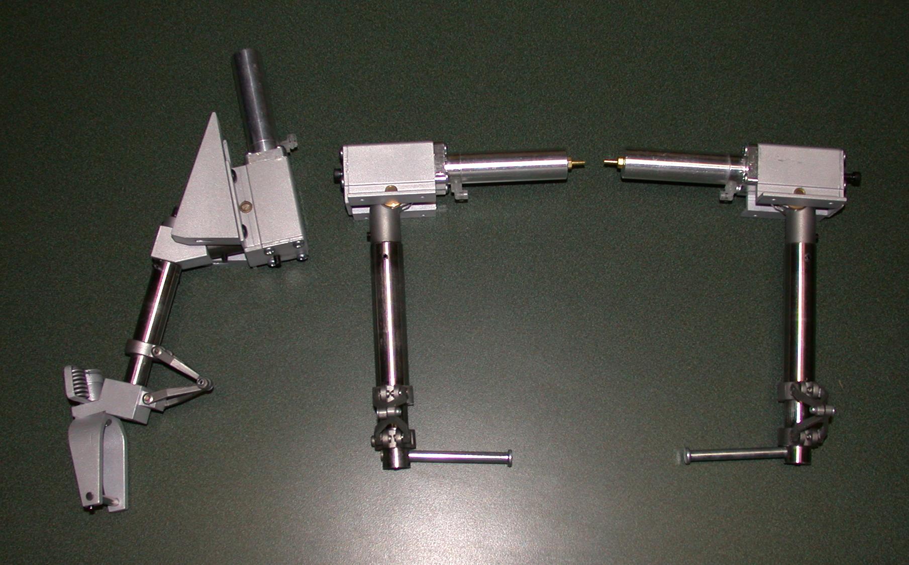
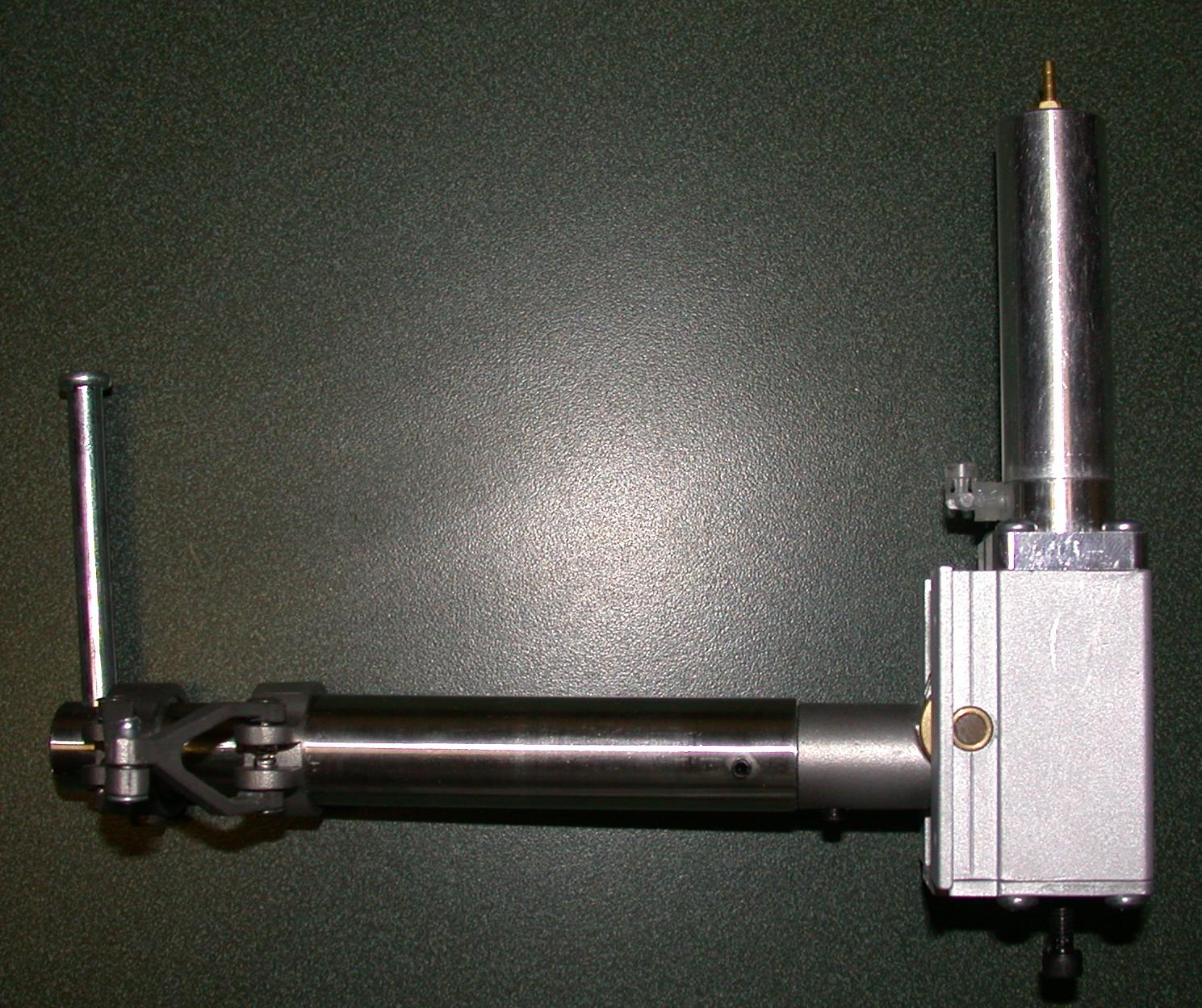
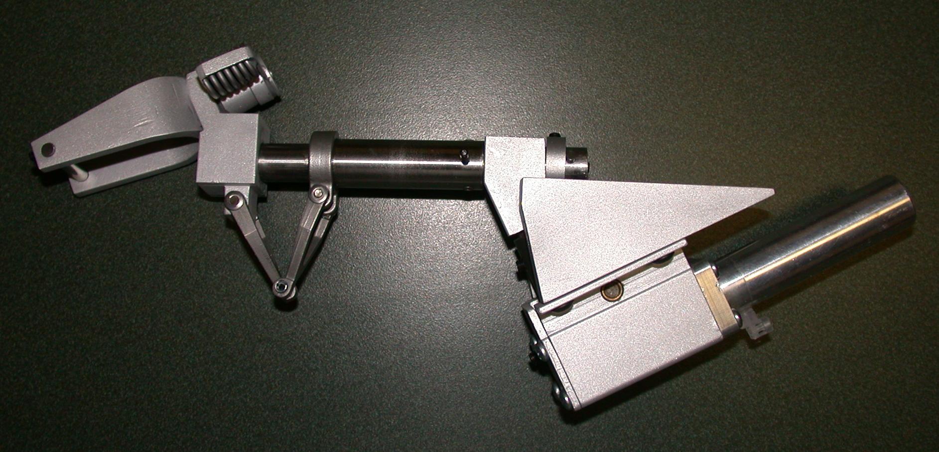
| Landing gear |
48 oz. |
| Wheels and brakes |
(20 oz.) |
| servos (10) |
(15 oz.) |
| Receiver and batteries |
(20 oz.) |
| Ballast (nose weight) |
(32 oz.) |
| Finish |
(20 oz.) |
| TOTAL |
(398 oz.) |
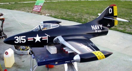
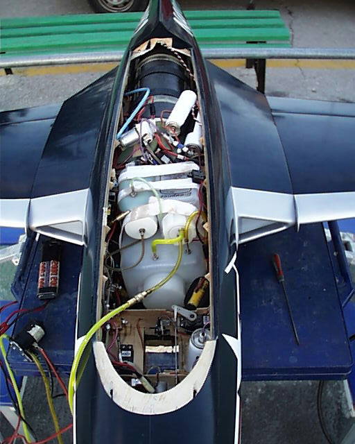
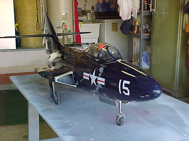
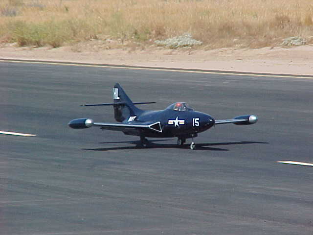
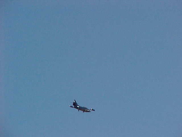
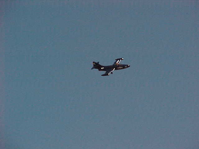
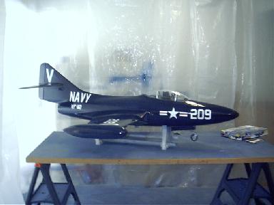
Here are a few pictures of Larry's Panther at the Fresno Jet Rally in September of 2002.

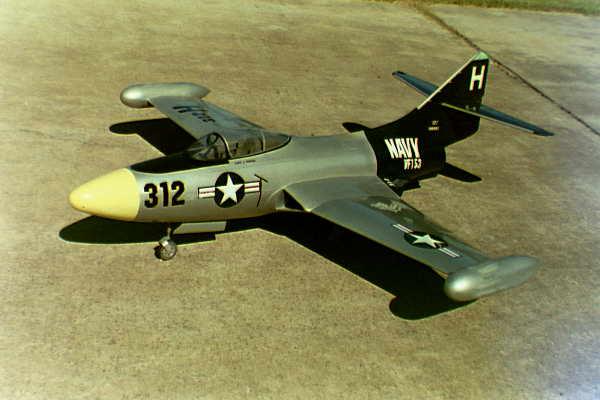
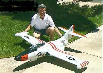
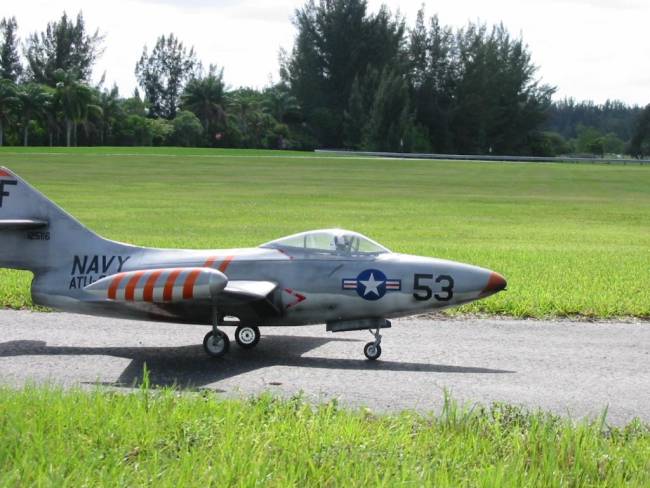
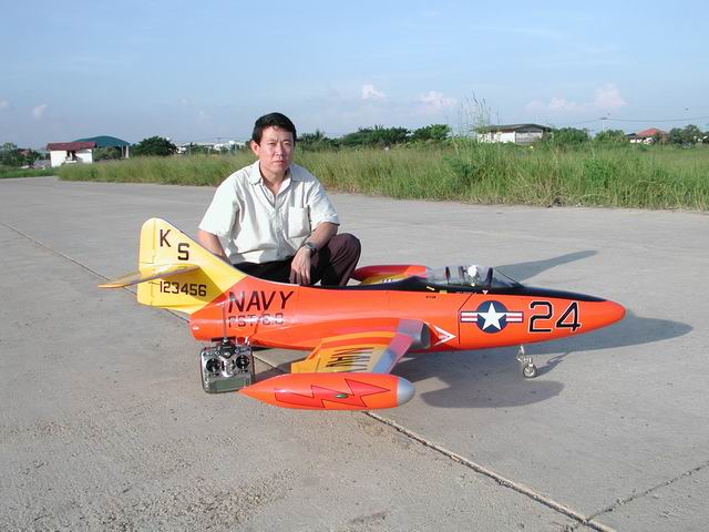
Here are some pictures of other Panthers in alternate paint schemes. Most of these are the same size as the Ziroli Panther, but are built from kits with fiberglass fuselages.