Pulses And Display Devices
- Pulse conversion
- Most signals/pulses detected on an imaging system are analog and my require digital conversion, known as analog to digital conversion (ADC)
- An analog peak is nothing more than a signal that represents a specific amount of voltage. The higher the peak, the greater the voltage. This signal is defined as any signal in which voltage changes with time.
- In order interface with a computer the signal must be converted
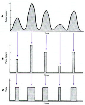
- The analog pulse is sent through a ramp converter that causes a capacitor to change the incoming signal. The time required for this discharge is measured with an internal clock. The digital pulse is given the same voltage value regardless of the pulse height. Variation in the pulse is expressed in the length of time the pulse is allowed to exist. See above diagram where A is the analog pulse, B represent its initial conversion and gives it a voltage value, and C shows the final ADC conversion where time is applied.
- Timing methods (SCA)
- Accurate time placement of an ionizing event also important. This becomes a concern when there are multiple PMT or in PET (coincidence detection)
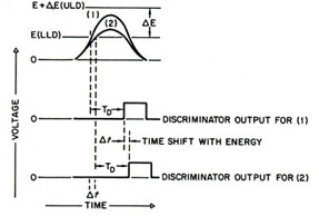
- The above example is known as leading-edge timing. In this scenario, the analyzer output occurs at a fixed time TD that occurs at the point time when the input pulse triggers the LLD. The problem with this approach is lack of some inaccuracy with timing (5-50 nsec with NaI crystal), because the output pulse depends on the amplitude of the input pulse. The variation in time is defined as ∆t and is known as timing walk.
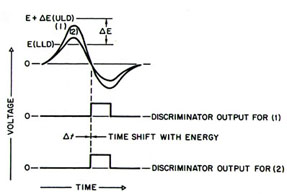
- Zero-crossover timing employs a faster timing technique. This requires a bipolar input pulse from a positive to a negative value. This method is less sensitive to pulse amplitude and provides a timing accuracy to within ± 4 nsec.
- Pulses and MCAs
- Sometimes imaging requires multiple voltage or energy windows events to be recorded. Such is the case with Ga67. Older systems usually have several SCA to record the different energy peaks, however, newer systems employ an MCA, which is more practical.
- How does an MCA work?
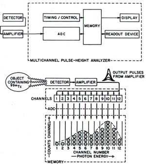
- ADC is the root of it all and it measures/sorts the incoming pulses and records the pulse based on its amplitude
- The amplitude range is usually between 0 10 V which is then subdivided into intervals or channels with a range of as few as 100 channels or as many as 8192. (consider this like a matrix, the greater the matrix the more channels you have)
- A system with 1000 channels would be V/1000 or 10/1000 = .01. Hence channel ones range is 0 0.01, channel two 0.01 0.02, etc.
- keV values are then assigned to the Voltage channel.
- The counts that are recorded are then stored in the systems memory
- This can then be replayed though a CRT screen or printed out as a hard copy.
- The system is seen below
- Role of high-voltage (HV)
- A slight change in HV on a GM will have little effect in this devices ability to record, however, a 1% change in a scintillation camera could result in a 10% change in the output pulse.
- The greatest effect of HV occurs with the PMT because of dynode multiplication
- Variation with HV can occur with temperature changes, variations in line voltage coming to the imaging unit, and the amount of current being drawn by the detector (known as output load) What happens to your imaging system when the hospital tests its generators? What role might there be for a battery backup? What can happen if there is a "brown out?"
- It is also important to note that HV power supply converted AC current to DC current. This causes the current to not alter, but be constant (direct current).
- Finally, there is something known as a "ripple." HV supply has a time-varying component with relatively small amplitude. The change in amplitude, ripple, is between 10 to 100 mV. A semiconductor camera will have a ripple <10 mV. This can cause problems. Ultimately, ripple will effect energy resolution, by changing the pulse height.
Return to the beginning of the document
Return to the Table of Contents
1/15