- Composed of high density (atomic number) materials which is required to "collimate" the incoming photons
- Lead is the most common element and the least expensive
- However, collimators can also be made of: tungsten, gold, depleted uranium, all of which are better attenuator when compaired to lead. Cost is another significant factor
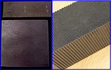
- Holes on the surface can be square, hexagonal, or round. Always closely packed together
- What hole design would you think best?
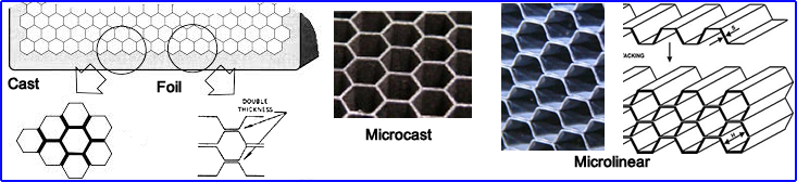
- More on design
- Foil collimators are composed of lead where septa are folded and glued together. Used with lower energy photons
- Cast collimators are casted and cut into its desired shapes. This is preferred when imaging medium and high energy photons
- Microcast collimators are made from molten lead and utilize pins to create the holes that keep the steel plates together
- Micro-linear collimators goes back to a foil concept, however, they are made at a slight angle to prevent misalignment of the septa
- Collimator application - There are four concepts one must apply when collimators are used to acquire data
- Geometric fraction (GF) - Those photons that do not interact with the collimation (are inside the umbra). They identify the correct XY coordinates (This is what we want!)
- Absorption fraction (AF) - The amount of photons that interact with the lead septa, causes them to slow down, then absorbed by the crystal, rejected at PHA (what region are these photons seen in spectrum containing the photopeak?)
- Penetration fraction (PF) - These photons have penetrated one or more lead septa, but are not attenuated enough, therefore cause scintillation and are accepted by the PHA. Results:
- Bad XY coordinates have been accepted
- Reduces contrast and an increase in background counts
- Scatter fraction (SF) - Photons that have scatter from interacting prior to reaching the collimator. Once it arrives at the collimator it does not interact with the septa, but is received by the crystal and accepted by the PHA
- Bad XY coordinates have been accepted
- Reduces contrast and an increase in background counts
- Resolution
- Is achieved by reducing the diameter of the hole in the septa
- Increasing septa length
- Sensitivity
- Septa have larger holes and shorter length
- Geometric faction is important, while the penetration fraction is not wanted
- Scatter fraction increases see below
- Rcoll diameter of the septa
- Reducing the diameter improves resolution and decreases sensitivity
- Increasing the diameter improves sensitivity, but decreases resolution
- HE/ME collimators usually have larger diameters to increase the amount of photons (remember usually less activity is injected). How does the crystal thickness play a role?
- Rleng
Septa length
- Increasing the length improves resolution and has little effect on reducing sensitivity (according to Perkeges). Your thoughts?
- Long-bore length (UHR) has applications in SPECT. Consider SPECT acquisition and how this might help
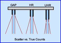
- True counts verses scatter

- So how does this image related to collimation when considering scatter and true counts?
- Click the image to get your answer
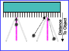
- Distance
- The greater the distance from the acquiring object the greater the area of the penumbra. This is where unwanted photons interact with the crystal giving the acquired counts a false location. To reduce this effect image as close to the patient as possible
- Umbra is the area that records the true location of the emitting photons
- There is no improvement with either sensitivity or resolution when you increased distance
- There is no magification effect when imaging closer to a patient if you are using a parrellel hole collimator
- Septa Thickness
- Thickness must increase with acquisition for higher energy gammas. This reduces the PF
- If the septa are not thick enough then septal penetration occurs
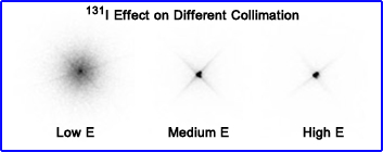
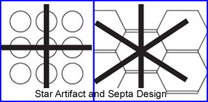
- This is referred to as the star artifact
- Star artifact is enhanced when there is high energy radionuclide within a small volume. Best example of this is imaging a patient with a large amount of 131I
- Another example of star artifact
- The weakest point in a HE collimator is between the centers of the holes which is where the PF is the strongest
- Based on PF penetrating the septa, the star artifact will reveal the type of septa within the collimator
- This chart shows the need to increase thickness of septa as the photon energy increase. Also realize that septal penetration increases even though thickness improves with higher energy collimators. If you designed a collimator to image 364 keV with <1% penetration what other "issues" might you have? (sensitivity/resolution)

Energy Rating of
the CollimatorSeptal
ThicknessSeptal
Penetration140 keV
0.25 mm
<1%
200 keV
0.5 mm
1%
364 keV
2.2 mm
>5%
- System resolution = collimator resolution (Rcoll) and intrinsic resolution (Rint)
- When considering system resolution and spatial resolution the most limiting factor is the collimator because lead septa reduces sensitivity and resolution. What other factors effect system resolution?
- Extrinsic resolution is what we shoot for that can be expressed as √ /R2int + R2coll
- Collimator resolution almost always dominates when it comes to system resolution
- System Sensitivity
- Intrinsic sensitivity is dependent on the thickness of the crystal
- The design of most cameras are 3/8 thick and have been engineered to capture 99mTc photon. Essentially most of the photons that interact are absorbed by the crystal
- If a higher energy photon is acquired, such as 131I, what factors could hypothetically need to be adjusted to improve camera sensitivity? (there are at least 2)
- Crystal thickness
- Use a ME collimator instead of a HE is noted in your textbook. What happens to PF as you switch from LE to ME to HE?
- Would injection of a lower dose help reduce PF?
http://www.vulcang
http://www.nuclearfields.comms.com/
- Types of collimators
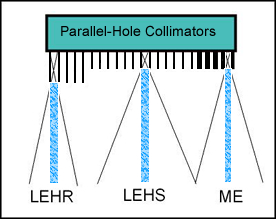
- Parallel hole - LEHS, GAP, LEHR, LEUHR, ME, HE
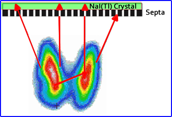
- On the surface of crystal a collimator is place to "focus" the incoming photons
- Incoming photons that fall within the "field of view" (pre/umbra) interacts with the crystal at the appropriate keV
- Demonstration of septal length
- Septa that are short in length allow a greater amount of photons and improve sensitivity, increasing counts - known as High Sensitivity (HS)
- Septa that are longer in length allow less photons from a reduced preumbra and improve resolution (reduce counts) - known as High Resolution (HR)
- Smaller septa diameters may also reduce counts but would improve resolution
- In general, the relationship between HS and HR is inversely proportional - you cannot have HS and HR in a collimator
- However, a collimator known as General All Purpose (GAP) scarifies both sensitivity and resolution
- Considering the thickness of a septa
- Thinner septa with higher energy photons cause penetrate to adjacent septa, crossover, and interact with the wrong area of the crystal and are recored, this is referred to as cross talk
- Therefore, septa thickness must increase as the energy photon increases in order to prevent cross talk from occurring
- Low Energy (LE) septa have a range of 100 - 200 keV
- Medium Energy (ME) septa have a range of 200 - 300 keV
- High Energy (HE) septa have a range of 300 or greater keV
- Distance of the collimator/detector (camera head) to the patient
- The closer the camera head is to the patient the better the resolution
- The further away from the camera head is from the patient the greater the loss of resolution since photons from the preumbra are being located at the wrong XY coordinates
- Consider the incoming photons and the septa's pre/umbra (refer to diagram)
- As the distances increases, the angle of the peumbra increases
- Anywhere a photon event occurs within the peumbra the coordinates are recorded if the photon is accepted by the PHA
- Only the area within the umbra are true counts
- Therefor it is VERY important to keep the collimator as close to the patient as possible
- In SPECT imaging UHR collimators may be preferred because the longer septa reduces the peumbra angle, thus reducing unwanted photons
- Other types of collimators
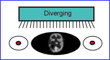
- Diverging
- Usually applied with cameras that have a smaller imaging area (<15 inches) which allows for acquisition area to have a larger FOV
- Moving the detector further away from the imaging source further increase area of acquisition
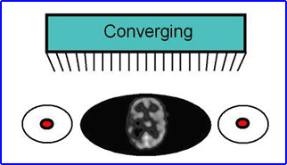
- Converging
- Used to magnify the area of interest and is the exact opposite effect of diverging
- Some collimators can be flipped resulting allowing the technologist to go between converging to diverging collimation
- Cone-beam collimators use the same principle for cardiac imaging so that a large field of view camera will magnify a smaller area of interest
- Increasing distance from the increases the area of acquisition
- Slant-Hole (usually 30o)
- Allows for a parallel view of an area of interest, but the septa are set at an angle
- In planar or SPECT brain scan it allows the technologist to reduce the distance. If a parallel hole collimator was used the patient's shoulders get in the way of a circular orbit resulting in increased distance between the patient and detector
- Note that resolution is best closest to the head of the camera.
- However, where the collimator is further away from the area of interest causes a loss in resolution. Umbra and preumbra can be drawn to prove this point
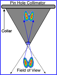
- Pinhole
- Used to magnify a very small area such as the thyroid
- In the process of acquisition the pinhole inverts any image that its acquiring and will magnify an object as it moves closer
- The hole in the pinhole collimator could be considered 1 large septa - THis aperture than may vary between 3 - 7 mm
- Some pinhole collimators have different size apertures that screw onto the collimator
- Some pinhole collimators have different aperture than can be screws on allowing for different diameters
- The smaller the diameter, the better the resolution, but fewer counts are acquired
- Resolution improves as the distance between the object decreases
- Do not place part of the acquisition at the edge of the FOV. It is at the edge of your detector your resolution is the worse.
- The thicker the object the greater the distortion
- Fan-beam
- Each row of septa have a focal point in one plain
- Adjacent septa are arranged in the same focal plain and in any given row they are parallel to each other
- This allows each independent row to focus on plain within 3D object
- When processed these rows generate individual tomographic slices
- Cone-beam
- All septa within all columns and rows are angled to one center focal point
- Similar to a converging collimator
- Each row across the center plain generates a tomographic slice
- Basic concepts to remember about collimation
- High Sensitivity (HS), High Resolution (HR); or General All Purpose (GAP)
- Low Energy (LE); Medium Energy (ME); or High Energy (HE)
- LE - Energy gammas of less than 200 keV
- ME - Energy gammas between 200 and 300 keV
- HE - Energy gammas greater than 300 keV
- Parallel, diverging, converging, pinhole
- From the above options for collimation consider the following characteristic a septa must have
- Length
- Angle
- thickness
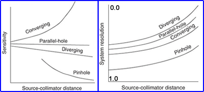
- Final point of interest on how different collimators respond to sensitivity and resolution and relate this to distance of an object being imaged. Look, compare and consider


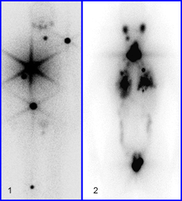
Looking at the two images below, two different patient received an 131I therapy dose and whole body images were obtained. What can you tell about the septa design, based on the star artifact?
2/19
Return to the Table of Contents
Objectives
- Identify methods in which collimators are made
- Foil
- Cast
- Microcast
- Miro-linear
- Define the components of a collimator as assessed by the following terms
- Geometric fraction
- Absorption fraction
- Penetration fraction
- Scatter fraction
- Resolution
- Sensitivity
- Rcoll
- Rlength
- Distance from an object
- Septa thickness
- Compare the imaging characteristics of different types of collimators
- LEHS
- GAP
- LEHS
- Ultra-LEHS
- ME
- HE
- Fan-beam
- Cone-beam
- Slant
- Pinhole
- Diverging
- Converging