- Causes of Nonuniformity
- Define uniformity - ability to reproduce a uniform distribution of radiation being detected. Consider this when assess a flood source that has uniform distribution and what causes it not be uniform
- Response to where the photon interacts with the crystal (above) will cause a lack of response as it approaches the edge of the PMT (photocathode)
- Where there are two PMT edges interact the positioning of the events are directed at each other further causing misposition of photon location

- Z-pulse variation from each PMT is another source of nonuniformity. Results in (Both a. and b.):
- Causes cold and hot PMTs
- Causes wavy lines
- Where there are two PMT edges interact the positioning of the events are directed at each other further causing misposition of photon location

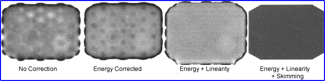
- Uniformity Corrections - nonuniformity can have as much as +/- 15% variation resulting is visual hot/cold spots
- Manually using a point source all PMTs can be tuned and this reduce nonuniform to about +/10%
- Count Skimming/Adding
- Determines the average counts per pixel from a uniform source
- Deviations per pixel are then stored
- As an image is collected counts are either subtracted (skimmed off) or added "on the fly"
- Every isotope used with this camera requires its own correction matrix
- Nonuniformity is reduced to about +/-5%
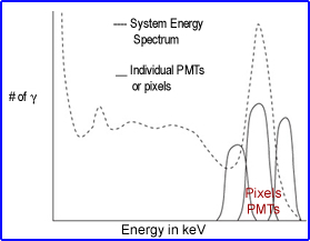
- Energy and linearity corrections
- Linearity corrections are stored at the pixel level usually at the factory or by service dude
- Energy peaks vary slightly at the PMT and pixel level
- Energy correction of the photopeak is applied at the pixel level with )Z
- When acquiring data these corrections factors are applied at the pixel level
- End results - improves energy resolution and reduces scatter
- Linearity correction
- Application of an appropriate linear phantom data is acquired in one projection to collect X coordinates. The system then creates )X to correct the positions which generates a straight line in the X direction
- Phantom is rotated 90 degrees to determine )Y positions applied
- Corrections are then applied to all pixels in the matrix
- End results
- Energy and linear corrections will generate a 3-5% non uniformity
- Adding count skimming, isotope specific acquisition with appropriate collimator will generate 1-3% nonuniformity
- Up to a 120 million count correction flood (sensitivity map) must be acquired to have a correction map
- Autotuning
- PMTs HV drift over time and autotuning is applied by making small adjustments as needed to assure that the variation of the pulse does not change
- Methods
- Photopeak monitoring - HV is monitored at PMT level and adjusted with a reference value
- Split-Photopeak monitoring - Each PMT has two high peak windows. When drifting occurs HV is adjusted by maintaining a ratio between the two peaks
- LED monitoring - LED flashes and generates photoelectron with the PMTs. The LED sets the standard and the PMTs adjust the HV when there is a drift in photoelectron collection
- If a PMT goes out of tune more than 3 keV then service dude takes over because the PMT can no longer correct itself
- Other points of interest
- PMTs are effected by magnetic fields and may be shields with mu-metal to reduce any low magnetic field. Would PMTs be able to function near an MRI unit?
- Keep your camera's room temperature constant with a suggested range of 68 to 70 degrees F.
- If temperature increases by 9 degrees or more within an hour the crystal may crack
- Beware of power surges and always use a batter backup
- Consider gamma ray photon interference from adjacent rooms and/or PET
- An old camera may show crystal hydration or optical gel deterioration
- Pixelated detector
- Has many small crystals, usually made of semiconductor material
- Each crystal is attached to a single position-sensitive photomultiplier (PSPMT)
- Collimator holes are lined up to individual crystals
- It's like creating a matrix on the detector head
- Resolution my not be as good, however, sensitivity is outstanding, and it allows for first pass procedures of the myocardium
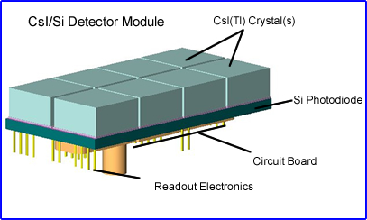
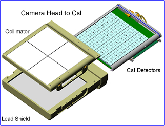
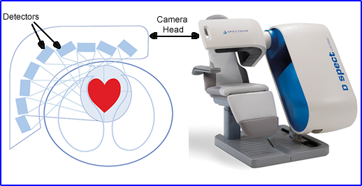
- CZT Camera (Cardiac)
- Pixeled system with CsI(Tl) crystals with silicon photodiodes
- There are 9 detectors in the camera head which rotate back and forth
- Has great counting statistics and shorten's imaging time
- Crystal materials
- NaI(Tl), CsI(Tl), CsI(Na), LaBr3 each have different properties (density, deadtime, light output, etc.)
- CZT is a semiconductor - better energy resolution and less thickness needed. It also has to operate below room temperature