- How does CT attenuation correct PET images?
- First let us review what we already know about x-rays
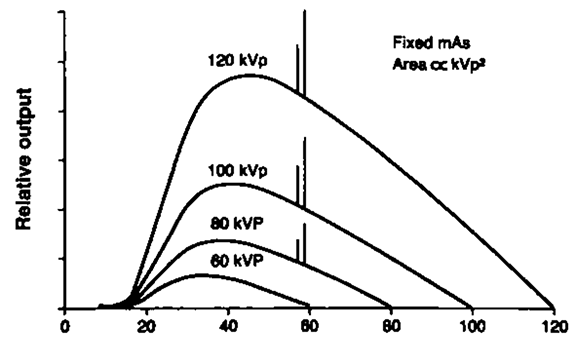
- The amount of x-rays being procedures depend on kVp, mAs, and time
- Increase in mAs results in the increase in the amount of x-rays being produced therefore increasing your radiation dose to the patient
- Increase in kVp causes an increase in the energy, increase in penetration, and an increasing radiation dose to the patient
- How do you prove contrast in an x-ray?
- What would you adjust if you the target being imaged had increased density?
- A look at different kVps and energies
- Why are some CT scanners classified as non-diagnostic in a PET imaging system?
- What is the role of automatic tube current modulation in a PET imaging system?
- The amount of x-rays being procedures depend on kVp, mAs, and time
- PE Kinahan and his associates1 published an article that points out what CT must do in order correct for attenuation in a PET scan. There are several components:
- Scaling CT to PET
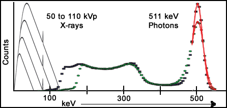
- PET 511 keV photons interact differently when compared to CT generated x-rays (70 - 140 kVp)
- Greater photoelectric and Compton interaction occur with the lower energy x-ray
- X-rays interact with air, water, and soft tissue have approximately 1.9 times greater Compton interaction when compared to 511 keV photons
- Photoelectric effect jumps to 13% when x-rays interact with bone , while PET has a 3% interaction
- Therefore, CT x-ray must be scaled up to reflect 511 keV interaction
- Monochromatic photons and polychromatic x-ray
- PET gamma rays always have the exact same energy
- CT x-rays vary in their energy beam by at least 1%
- Results in an alteration of the attenuation coefficient
- Segmentation
- This is a process in which attenuated CT values are converted to known u values which is based on the tissue types
- Given a certain threshold with the CT x-ray, specific tissue types are identified: bone, soft tissue, and lung
- One minor problem with this approach occur when there is a variation of tissue types in a given area ... example - lungs contain several different : values
- Once the different tissue types are identified Scaling and Segmentation can be applied
- Segmentation defines the specific organ or tissue type and applies the correct attenuation coefficient
- Scaling for bone, soft tissue, and air will further adjusts the attenuation map to reflect the correct amount of 511keV photons
- Consider photons being emitted from the lungs. This causes less attenuation which CT corrects by subtracting photons
- Consider photons being emitted from bone. This causes greater attenuation which CT corrects by adding photons
- Scaling CT to PET
- Application of CT attenuation in PET
- Increased density
- Causes higher CT attenuation coefficients
- Increased attenuation of the PET photons also occur
- The net result - CT adds PET photons to compensate
- Decreased density has the opposite effect
- In addition co-registration is essential for CT to correct these images
- Matrix size must be adjusted
- CT = 1024 x 1024
- PET = 128 x 128
- Matrix size must be adjusted
- Increased density
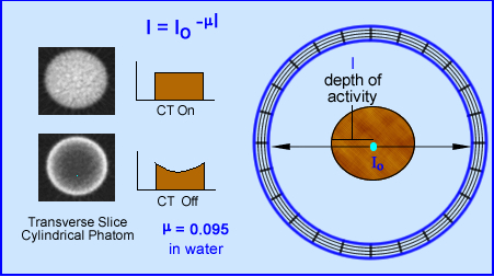
- In theory the above application shows how photons are attenuated in a water filled phantom
- The closer to the center the greater the amount of photons are attenuated
- Closer to the surface of the cylinder the less the attenuation and greater concentrations of photons are emitted
- End result is the above image which should show a homogenous mixture of radioactive fluid
- However when you apply an attenuation correction, from CT, the fluid from the transverse profile look homogenous
- So what does an PET image look like with and without attenuation?
- Surface area is hotter
- Lungs show increased activity
- Inner portions of the body is "colder" in relationship to an increase in density
- Here is an example of what the corrected and uncorrected images look like click here
- This is a second example of PET scan that has attenuation correction (avi file)
Metal and implants located in the body habitus- Many types of implants are made of a metallic substances. Metal translates to a high attenuation coefficient (even higher than bone)
- High density materials, such as metal, cause increases in attenuation of the CT x-rays. In turn, excessive amount of photons are added to the PET image
- From a CT standpoint usually a streaking artifacts is seen. This is especially true with metal objects. Seeing a streaking artifact on CT should immediately clue you to the fact that false alteration of CT attenuation is about to happen!
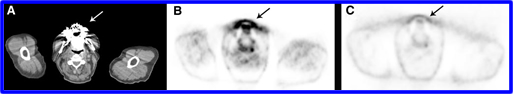
Reprint Permission Granted - Society of Nuclear Medicine - Our first example shows metal interfering with the area of the mouth (dental work)
- CT image (A) shows striking from the dental work creating an artifacts
- (B) is the PET image with attenuation correction on. If the patient had head and neck cancer, would this be considered positive?
- This is a situation where the image must be evaluated with CT correction turned off. Refer to (C)
Reprint Permission Granted - Society of Nuclear Medicine
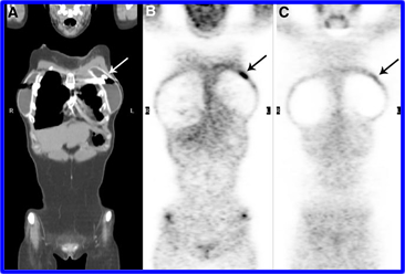
- This is an example of where the technologist fails to instruct the patient to remove ALL her jewelry
- A metal object is noted on CT scan. Further investigation reveals that it is a nipple ring (A)
- When attenuation correction is applied (B) a correlating hot spot is noted on the patient's breast
- Applying the uncorrected PET image (C) gives the oncologist a sigh of relief
Reprint Permission Granted - Society of Nuclear Medicine- What happens with patient that have a hip prosthesis?
- To appreciate what is being seen note that the implant does not pick up FDG (A}
- When CT attenuation is not applied (B) the area remains cold. Why?
- No FDG activity within the prosthesis
- High : value in CT is multiplied by zero PET photons resulting in a void of activity
- Unrelated observations
- If you had not been told which image was AC'ed, which one would you identify?
- Look at the lung/liver activity
- Look at the activity at the surface of the skin
- Muscle activity in legs
- Activity in the center of the patient (liver)
- From a CT standpoint usually a streaking artifacts is seen. This is especially true with metal objects. Seeing a streaking artifact on CT should immediately clue you to the fact that false alteration of CT attenuation is about to happen!
Contrast - Venous and Oral contrast- Contrast agents, either IV and oral are attenuating compounds. What happens when CT and PET get involved with contrast?
- Iodine and barium increase attenuation within the body habitus. This increases attenuation results in an increase in the attenuation coefficient, meaning an amplification of in count density when attenuation correction is applied
- The specifics of IV contrast
- Usually IV contrast agents are quickly filtered out of the body as well as quickly diluted by the patient's vascular system. As a general rule, CT attenuation with IV contrast should not create any issue .
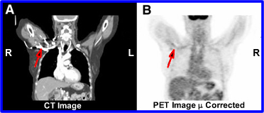
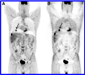
Reprint Permission Granted - Society of Nuclear Medicine - However, if contrast is still is in the vascular pool when the CT images are acquired, attenuation coefficients for PET alter the photon density
- The red arrow in (A) shows contrast in the CT scan
- The red arrow in (B) shows falsely high counts in the AC PET images
- To solve this problem use the non-contrast CT images for your attenuation correction
- Usually IV contrast agents are quickly filtered out of the body as well as quickly diluted by the patient's vascular system. As a general rule, CT attenuation with IV contrast should not create any issue .
- When considering oral contrast what happens with chyme as it moves through the GI tract .. water is removed increasing the density of the remaining material
- Add barium sulfate to the mix and you have an great attenuator
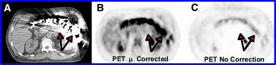
Reprint Permission Granted - Society of Nuclear Medicine - As noted in the above images these higher u values cause an over correction of counts with the PET data (B). However, with the raw data (C) a false positive diagnosis is prevented
Truncation- Truncation happen when CT's FOV ends and PET FOV continues
- At this cutoff point - AC no longer occurs and increased activity is noted in then PET scan. Can you explain why?
- Sometimes truncation can be prevented when the patient's arms are placed over the head
- However, in bariatric patients, truncation is usually unavoidable
- The following images shows how truncation effects the outer potions of the body
- At MCV the CT's FOV is 50 cm in diameter and the PET's FOV is 70 cm in diameter
- Lack of CT u values and an increase of photons are being detected
- Furthermore, more photons are being emitted closer to the surface of the body
Mis-Registration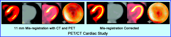
http://jnm.snmjournals.org/content/48/2/188/F5.expansion.html- Misalignment of CT attenuation in a PET scan may cause the wrong subtraction or addition of PET photons
- In this case the mis-registration causes counts to be subtracted from the PET data resulting in a defect in the apex of the LV
- Misalignment of CT is usually caused by patient motion. Correcting for the alignment issue shows normal distribution in the apex
Motion artifacts from breathing- Can we prevent the breathing artifact in CT/PET?
- When a CT scan acquires images of the chest several a motion artifact is probable
- Breath hold image as CT is acquired over the chest.
- However, PET acquisition cannot be acquired in the same manner
- This causes subtraction of photons where there is lung movement
- Several ideas on how to blend the CT image with PET- that don't really work
- Take a deep breath and hold it during CT acquisition
- Take a mid-breath and hold it during CT acquisition
- Take shallow breaths during CT acquisition
- If only patient could hold his/her breath long enough in a PET scan to match the holding breath on CT
- What actually causes the defect? Lower attenuation values in CT are identified by the lung tissue in the area, however, in PET lung tissue moves in and out at its base. This results in a subtraction of counts because CT defines the area of having less density
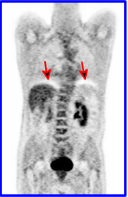
Reprint Permission Granted - Society of Nuclear Medicine- The example shows arrows point to two photopenic curves at the base of the lung, where the patient's diaphragm is located
- In this scenario the patient was asked to take a deep breath and "hold it" during the CT acquisition
- During PET acquisition the patient was breathing normally causing the subtraction of photons at the base of the lungs
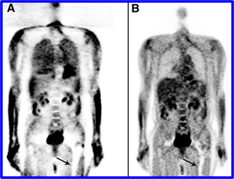
Reprint Permission Granted - Society of Nuclear Medicine - This study finds a questionable lesions at the base of the lung
- (A) Shows the AC PET images with a lesion located in the middle of the motion artifact
- (B) The raw PET image shows the lesion is actually located in the liver
- Therefore, always look at your raw data
- What actually causes the defect? Lower attenuation values in CT are identified by the lung tissue in the area, however, in PET lung tissue moves in and out at its base. This results in a subtraction of counts because CT defines the area of having less density
- When a CT scan acquires images of the chest several a motion artifact is probable
Return to the Beginning of the Document
Return to the Table of Content
2/23
The majority of this presentation came following article: PET/CT Imaging Artifact by Sureshbabu, W and Mawlawi O, Journal of Nuclear Medicine Technology Volume 33, Number 3, 2005 156-161
For more information on how CT attenuation works with PET I suggest you read, "Attenuation correction for a combined 3D PET/CT scanner" by P. E. Kinahan,a) D. W. Townsend, T. Beyer, and D. Sashi